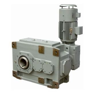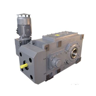
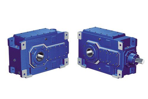
to withstand axial forces including those caused B3-HH-18-D Bevel-helical gearbox B3
In stock
SKU
B3-HH-18-D
$117,750.00
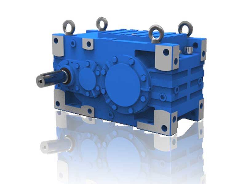
Flender/Flender Gear Units/Bevel-helical gearbox B3
provided for. The flow direction of the pump used is independent of the direction of rotation , if nothing is specified in the documentation to the contrary. When connecting the fittings the actual flow direction must however be observed. 2
  1 1 5 6 H2. 1 H2. 1 Fig. 3: Air oilcooling system on gear unit of type H2. 2
  2 5 3 5 6 B2. 1 B2. 1 Fig. 3: Air oilcooling system on gear unit of type B2.
  1 Flange pump 4 Double changeover filter 2 Pressure monitor (circuit diagram see item 5.5. 5 Air oilcooler 3 Coarse filter 6 Temperaturecontrol valve Depending on the application, the flange pump may have been replaced with motor pump. detailed view of the gear unit can be obtained from the drawings in the gearunit documentation. 4 / 1BA 5 en 0/2When installing gear units with addon air oilcooling units, it must be ensured that the air circulation is not obstructed. The required minimum distance from adjacent components, walls, etc. is indicated in the drawings in the unit documentation. Addon pressure monitors must be connected as shown in item 5.5.2. When operating and servicing the components of the oilsupply system, observe the operating instructions of the components. For technical data, refer to the data sheet and/or the list of equipment. The cooling effect is considerably reduced if the cooler or the gear housing are dirty (see section 1, "Maintenance and repair"). 5.8.4 Addon oilsupply unit with water oilcooler For types H2.. and B2.., an oilsupply system with water oilcooler may be applied, if required in the order. This is permanently attached to the gear unit. Components: pump water oilcooler pipework Depending on size and/or orderspecification the oilsupply system with water oilcooler may in addition include the following components: filter monitoring equipment The flow direction of the pump used is independent of the direction of rotation , if nothing is specified in the documentation to the contrary. When connecting the fittings the actual flow di
| Model Type | Bevel-helical gearbox B3 |
|---|---|
| Gear Type | Bevel Helical Gear |
| Weight (kg) | 5495.000000 |
| Ratio Range | 1 : 14…80 |
| Low Speed Output | Hollow shaft with keyway acc. to DIN 6885/1 |
| Nominal Torque | 240000 Nm |
| Mounting Arrangements | Horizontal mounting position |
| Manufacturer | A. Friedr. Flender AG & Co. KG |
| Country of Manufacture | Russia |
| Data Sheet & Drawings | to withstand axial forces including those caused B3-HH-18-D Bevel-helical gearbox B3 |
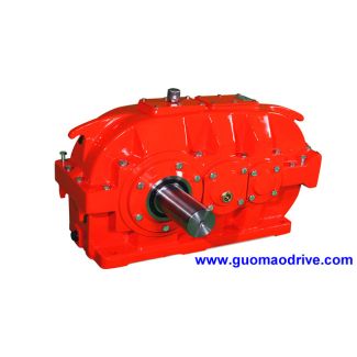
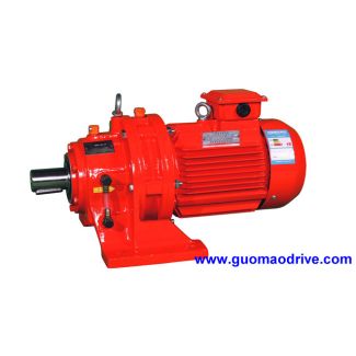
Related Products