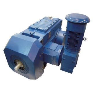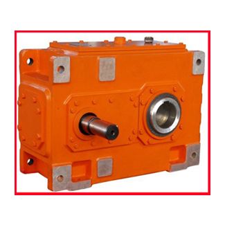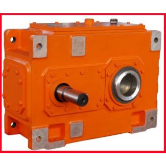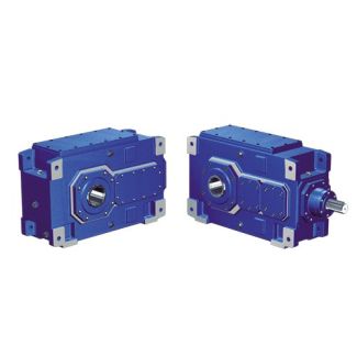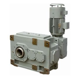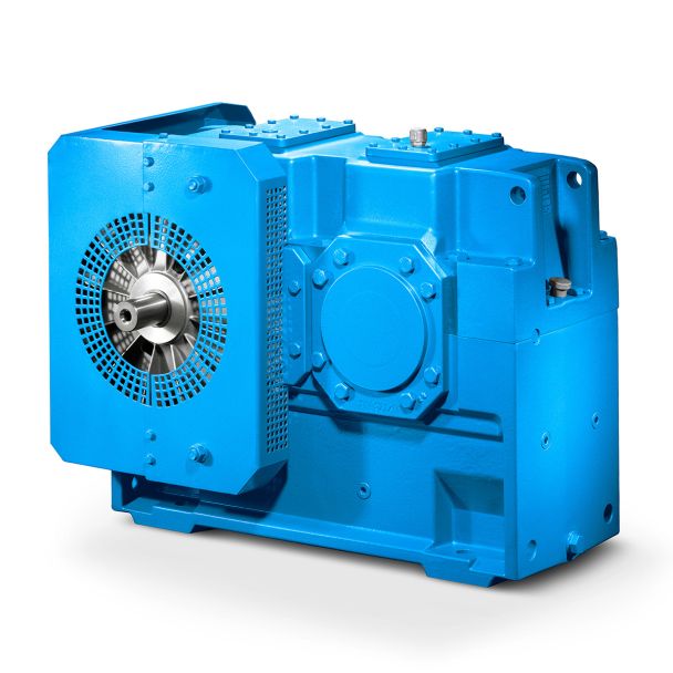

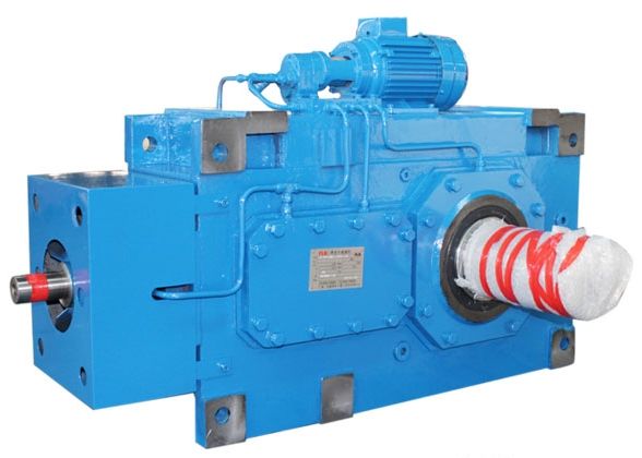
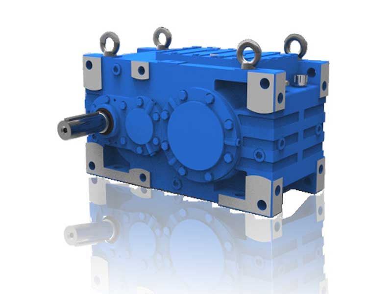
onwards For details on the shafts see Chapter B3-HH-17-D Bevel-helical speed reducers B3
In stock
SKU
B3-HH-17-D
$106,928.57
Flender/Flender Gear Units/Bevel-helical speed reducers B3
Property damage Damage to the cooling coil is possible.The pressure of the cooling water must not exceed 8 bar . The ends of the cooling coil must not be twisted and the reducer screws must not be removed. When there
  is risk that the cooling water will freeze the cooling water must be drained and the residual water must be
  blown out with pressurised air.The water can flow through the gear unit in either direction.In order to prevent an excessive
  water pressure on the cooling water inlet, suitable cooling watercontrol must be applied (. . by means of pressure reducer or an appropriate locking valve). WARNING Risk of injury to the eyes from pressurised air Residual water and/or dirt particles can injure the eyes.Wear suitable protective glasses. Note For connection dimensions, refer to the dimensioned drawing of the gear unit. The requiredcooling-water quantity and the maximum permissible inlet temperature are given on the data sheetand/or the list of equipment. For detailed illustration of the gear unit and the position of the add-on parts, please refer to the drawings in the gear unit documentation. 3 / 9BA 5 en 0/2.9.3 Separate or external oil supply system An oil supply system, which is supplied separately by Siemens, or an external system can be used for cooling the oil. Note Be sure to observe the operating instructions of the oil supply system for operation and maintenance. Note When operating and servicing the components of the oil supply system, observe the operating instructions of these components.For technical data, refer to the data sheet and/or the list of equipment. 5.1 Couplings For the connection of the drive machinery (motor) and the gear unit, generally elastic couplings or safety couplings are used. If rigid couplings or other in- and/or output elements, which create additional radial and/or axial forces, (. . gear wheels, belt pulleys, disk flywheels, hydraulic couplings) are to be used, this must be agreed by contract. 5.1 Heating At low tem
| Model Type | Bevel-helical speed reducers B3 |
|---|---|
| Gear Type | Bevel Helical Gear |
| Weight (kg) | 4990.000000 |
| Ratio Range | 1 : 12.5…71 |
| Low Speed Output | Hollow shaft with keyway acc. to DIN 6885/1 |
| Nominal Torque | 200000 Nm |
| Mounting Arrangements | Horizontal mounting position |
| Manufacturer | Flender GmbH |
| Country of Manufacture | Portugal |
| Data Sheet & Drawings | onwards For details on the shafts see Chapter B3-HH-17-D Bevel-helical speed reducers B3 |
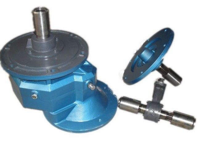
Related Products