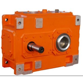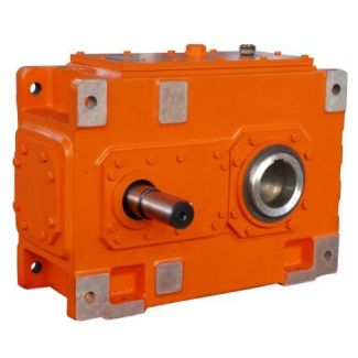
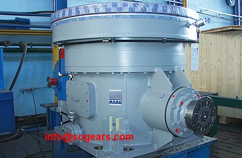
caused by weight of gear unit on request Flender B3-FV-25B Bevel-helical gear boxes B3
In stock
SKU
B3-FV-25B
$345,000.00
Flender/Flender Gear Units/Bevel-helical gear boxes B3
sion error curve versus the measured angular position and in the frequency/order range in the form of spectra. Averaging over one revolution of the pinion or the wheel serves to identify transmission error components which are caused by the wheel
  or the Fig. 7.9 Principle of the single-ank test7.2 Testing Bevel Gear Sets 3 pinion. The top half of Fig.
  7.1 shows an example of transmission error curve averaged for one revolution of the wheel. In ISO 1:2, four objective
  parameters are dened for the single-ank test. The total single-ank composite deviation F0irepresents the difference between the maximum and minimum transmission error. low pass lter with window of three tooth contacts provides centering linear curve of the trans- mission error signal. This long-term component of the transmission error supplies the corresponding parameter f0l. The difference between the complete signal and the long-term component yields the short-term component of the single-ank deviation. The maximum deviation within tooth contact is the tooth mesh component f0i. In many cases different analytical method is used. As in acoustics, the transmission error signals are subjected to Fast Fourier analysis and related to the rotational speed of the wheel. strong dominance of the tooth mesh order and its harmonics is characteristic of the resulting order spectrum [ MARQ9 ,VDI0 ]. The transmission error can be indicated as an angle. Alternatively, it can be given as an arc length, the gear diameter of the pitch cone at the calculated point being given as the reference diameter [ VDI0 ]. The advantage of this form of representation is that the transmission error curves are simpler to compare with the ease-off. Another option is to level the transmission error on reference value. As in acoustics, where measured sound pressure or structure-borne noise signals are shown in leveled form, this facilitates the comparison of signal curves. Averaging for single tooth mesh eliminates virtually al
| Model Type | Bevel-helical gear boxes B3 |
|---|---|
| Gear Type | Bevel Helical Gear |
| Weight (kg) | 16100.000000 |
| Ratio Range | 1 : 20…71 |
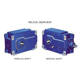
| Low Speed Output | Flanged shaft |
| Nominal Torque | 860000 Nm |
| Mounting Arrangements | Vertical mounting position |
| Manufacturer | Siemens AG |
| Country of Manufacture | China |
| Data Sheet & Drawings | caused by weight of gear unit on request Flender B3-FV-25B Bevel-helical gear boxes B3 |
Related Products