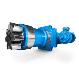
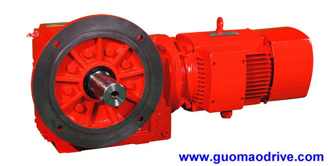
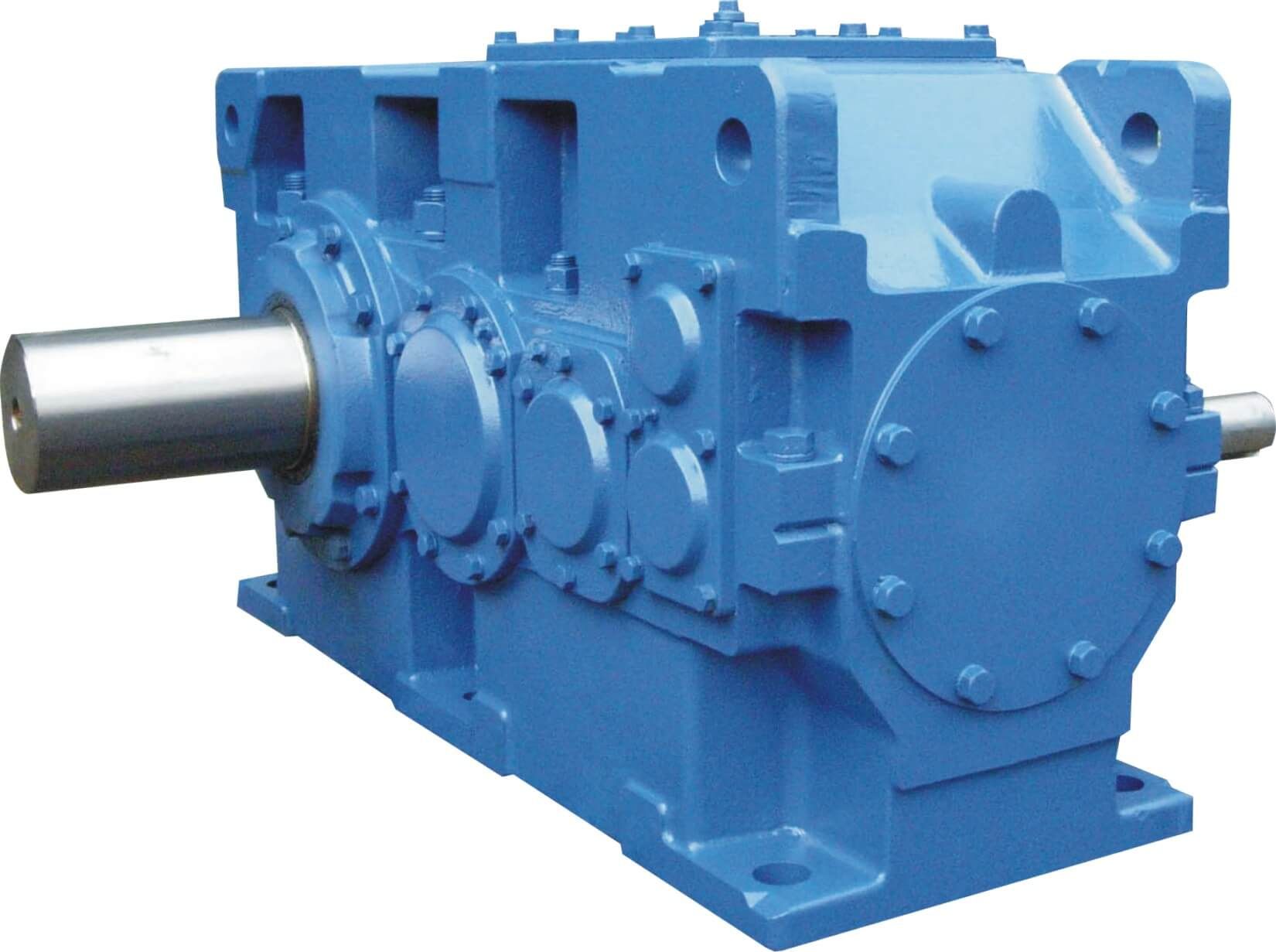
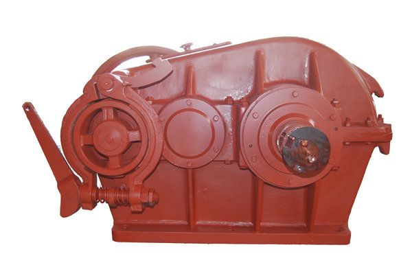
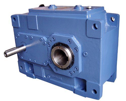
B3-CV-10B on Type H Gear unit dimensions threest age gear Bevel-helical gear reducer B3
In stock
SKU
B3-CV-10B
$19,928.57
Flender/Flender Gear Units/Bevel-helical gear reducer B3
pect to mounting . Blank For units not supplied prelubricated . 1-6 See pages 1 and 1 . Output Bore CodeSpecified in 1/1 increments . See page 1 for complete offering . Example 1 1/4 = P2 For Series only
  . How to Order When ordering reducers please include code letters for Style, Size, Base (if required), Ratio, Fan (if
  required), Lubrication (if required), NEMA Mounting (if flanged reducer), Shaft Assembly and Motor (if required) . EXAMPLE: Required size, 7
  Quill types flanged reducer, 3:1 ratio, 5/8 input bore, standard assembly, with horizontal base, no lubrication . Motor to be 3/4 HP , 1 RPM, 2/4 Volt, 3 Phase, 6 cycle, open dripproof . 7 3 B5 GUB3 1 . Reducer, Base and Motor Shipped separately: ORDER: Reducer - F7-3-B5- Base Kit - 5 Motor - GUB3 2 . Reducer, Base and Motor assembled: ORDER: F7B-3-B5--GUB3Style Size Base Ratio Fan VentOil SealsLubricationNEMA MountingShaft AssemblyMounting PositionOutput Bore Code -1-BG 5/1 FLENDER GRAFFENSTADEN bostongear speed reducersASingle Reduction Speed Reducer Selection Procedure To properly select speed reducer, the following application information must be known: Input RPM (Ratio) Output Torque Input Horsepower Service Factor Non-Motorized Speed Reducer 1 . Determine service factor from table below . 2 . Determine design horsepower . Design Horsepower = Application Load Service Factor 3 . Select speed reducer size that satisfies output RPM, service class and/or output torque requirements . 4 . Check overhung load capacity . Motorized Speed Reducer 1 . Determine service class from table below . 2 . Select reducer size that satisfies output RPM, service class and/or output torque requirements . 3 . Check overhung load capacity . Service Factor Table AGMA Class of ServiceService Factor Operating Conditions 1.0Moderate Shock-not more than 1 minutes in 2 hours. Uniform Load-not more than 1 hours per day. II1.2Moderate Shock-not more than 1 hours per d
| Model Type | Bevel-helical gear reducer B3 |
|---|---|
| Gear Type | Bevel Helical Gear |
| Weight (kg) | 930.000000 |
| Ratio Range | 1 : 16…90 |
| Low Speed Output | Solid shaft without parallel key |
| Nominal Torque | 43800 Nm |
| Mounting Arrangements | Vertical mounting position |
| Manufacturer | A. Friedr. Flender AG & Co. KG |
| Country of Manufacture | Germany |
| Data Sheet & Drawings | B3-CV-10B on Type H Gear unit dimensions threest age gear Bevel-helical gear reducer B3 |
Related Products