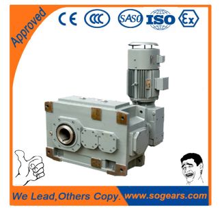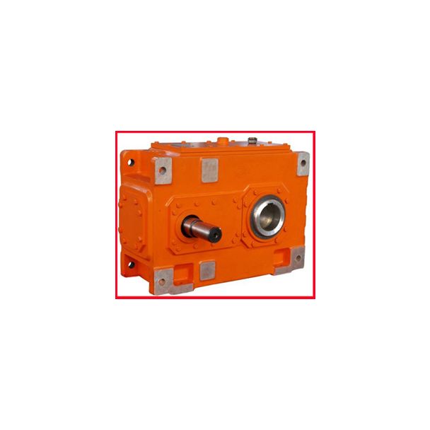
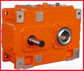

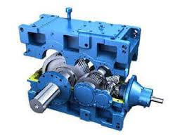
B2CH-16-C ign of the gear units Overview tables Type B Nomi Bevel-helical gear reducers B2
In stock
SKU
B2CH-16-C
$18,750.00
Flender/Flender Gear Units/Bevel-helical gear reducers B2
mensioning is possible. The cubic mean value for the consideration of the load distri- bution for variable load in representative period of time "" is calculated for: For this, P1 ... Pn is the operating cycle in the time cycle
  t1 ... tn. Helical gear units Type H3 and H4 for crane applications (sizes 5 to P1P +3 . Pn
  Pt1 ttn Classification of the driving gears into groups Crane type DesignationType of driving gear Hoisting gear Retractable luffing gear
  Assembly cranes M2 ... M3 M1 ... M2 Workshop cranes M6 Slipway cranes, dockyard cranes, disassembly cranes M5 ... M6 M4 ... M5 Harbor cranes (rotatable, on portal, etc.) Floating cranes and floating shearing cranesM6 ... M7 M5 ... M6 Collective Cubic mean valueService factorsOperating service life class T0 T1 T2 T3 T4 T5 T6 T7 T8 T9 Total operating time in hours 1 > 2 4> 4 8> 8 1> 1 3> 1 6> 6 1> 1 2>2 5> 5 L1 0.4 f1 1.1 M1.1 M1.1 M1.1 M2.1 M3.1 M4.1 M5.1 M6.1 M7.2 M8 f3,stat0.6 0.6 0.6 0.6 0.6 0.6 0.6 0.6 0.6 0.6 L2 0.5 f1 1.1 M1.1 M2.1 M1.1 M3.1 M4.1 M5.1 M6.1 M7.2 M8.5 M8 f3,stat0.6 0.6 0.6 0.6 0.6 0.6 0.6 0.6 0.6 0.6 L3 0.6 f1 1.1 M1.1 M3.1 M2.1 M4.1 M5.1 M6.1 M7.3 M8.5 M8.6 M8 f3,stat0.6 0.6 0.6 0.6 0.6 0.6 0.6 0.6 0.6 0.6 L4 0.8 f1 1.1 M2.1 M4.1 M2.1 M5.1 M6.1 M7.3 M8.6 M8.7 M8.0 M8 f3,stat0.6 0.6 0.6 0.6 0.6 0.6 0.6 0.6 0.6 0.6 recalculation is absolutely required for the following gear units: H3 size 6 = 3.5 to 4 H3 size 1 = 2 to 5 H3 size 1 = 3.5 to 5 H3 size 1 = 2.4 H3 size 2 = 2.0 0.4 0.1Load G_MD2_EN_0 Operating time1.7 3.3.0 0.7 0.4 0.2.4.0 1.0 0.8T 1 P1 2 P2 3 P3 t1 t2 t3 t1 t1 t1 t2 t2 t2 t3 t3 0 1 5 1 0 5 1 1 5 0 1 0L 1 4 3 2 For H3 size 1, recalculation is required. Flender GmbH 2NER GROUP CO.,LIMITED Germany sogears HB series gearbox 3/1 Flender MD 2.1 2Design of the gear units Overview tables Type H1 Nominal power rating of gear unit sizes 3 to 1 Technical specifications Nominal power ratings P2N (kW) type H1 Forced lubrication required for horizontal g
| Model Type | Bevel-helical gear reducers B2 |
|---|---|
| Gear Type | Bevel Helical Gear |
| Weight (kg) | 875.000000 |
| Ratio Range | 1 : 5.6…20 |
| Low Speed Output | Solid shaft without parallel key |
| Nominal Torque | 148000 Nm |
| Mounting Arrangements | Horizontal mounting position |
| Manufacturer | A. Friedr. Flender GmbH |
| Country of Manufacture | China |
| Data Sheet & Drawings | B2CH-16-C ign of the gear units Overview tables Type B Nomi Bevel-helical gear reducers B2 |
Related Products