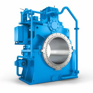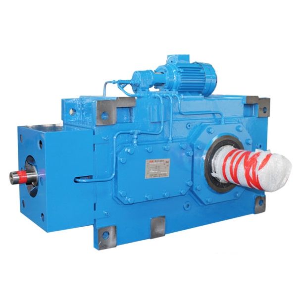
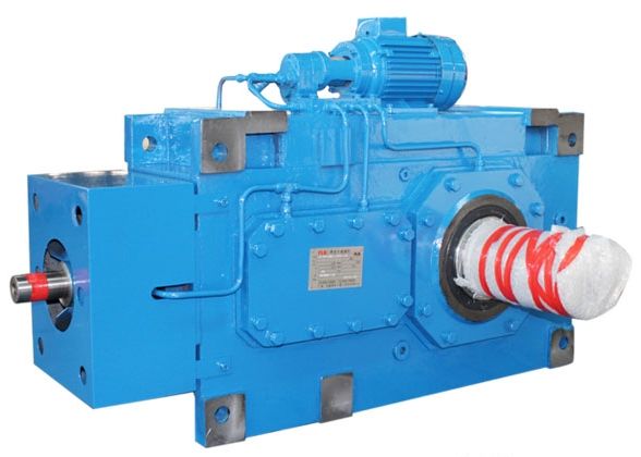
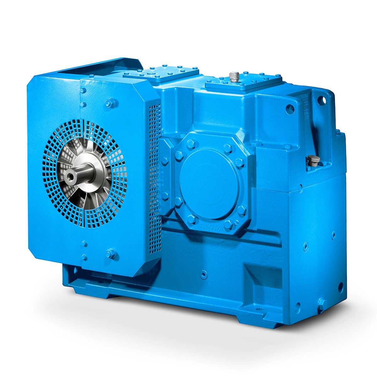
Flender GmbH Flender MD Design of the gear B2-VV-13-A Bevel-helical gear Reduction Box B2
In stock
SKU
B2-VV-13-A
$74,464.29
Flender/Flender Gear Units/Bevel-helical gear Reduction Box B2
machine shaft, see dimensioned drawing in the gear unit documentation). 6.7.1 Preparatory work To facilitate demounting (see also item 6.6.3.), we recommend providing connection for pressure oil on the end of the driven machine shaft. For this hole must be
  drilled through to the hollow shaft bore. This connection may also be used for supplying rustreleasing agent. 6.7.2 Fitting Remove
  the preservative agent from the hollow shaft and the machine shaft with suitable cleaning agent (such as benzine). Do not
  allow the cleaning agent (.. benzine) to contact the shaftsealing rings. Ensure adequate ventilation. Do not smoke! Danger of explosion! Check the hollow and machine shafts to ensure that seats, teeth or edges are not damaged. If necessary, rework the parts with suitable tool and clean them again. Coat with suitable lubricant to prevent frictional corrosion of the contact surfaces. 6 / 1BA 5 en 0/2.7.2.1 Fitting with integrated DU bush Fit the gear unit by means of nut and threaded spindle. The counterforce is provided by the hollow shaft. The hollow shaft must be exactly aligned with the machine shaft to avoid canting. When fitting, ensure that the position of the teeth between the machine shaft and hollow shaft is correct. The correct position can be determined by turning the input shaft and/or by swivelling the gear unit lightly around the hollow shaft. 7 5 6 Fig. 5: Hollow shaft with internal spline, mounting with DU bush 1 Machine shaft 4 Nut 7 End plate 2 Hollow shaft 5 Threaded spindle 3 DU bush 6 Nut 6.7.2.2 Fitting with loose DU bush The loose DU bush is pushed onto the machine shaft, fixed rigidly in position with locating tie and then pulled into the hollow shaft along with the machine shaft (see fig. . The hollow shaft must be exactly aligned with the machine shaft to avoid canting. When fitting, ensure that the position of the teeth between the machine shaft and hollow shaft is correct. The correct position can be determined by turning th
| Model Type | Bevel-helical gear Reduction Box B2 |
|---|---|
| Gear Type | Bevel Helical Gear |
| Weight (kg) | 3475.000000 |
| Ratio Range | 1 : 5…18 |
| Low Speed Output | Solid shaft with parallel key acc. to DIN 6885/1 with reinforced spigot |
| Nominal Torque | 81100 Nm |
| Mounting Arrangements | Vertical mounting position |
| Manufacturer | Flender France S.A.R.L. |
| Country of Manufacture | Singapore |
| Data Sheet & Drawings | Flender GmbH Flender MD Design of the gear B2-VV-13-A Bevel-helical gear Reduction Box B2 |
Related Products