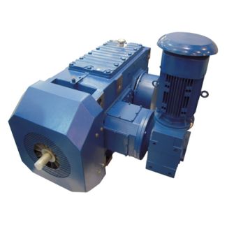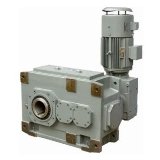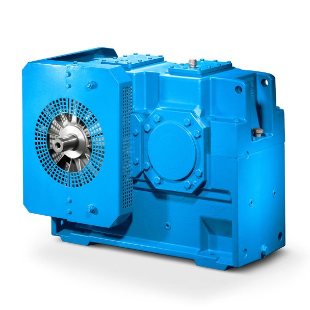

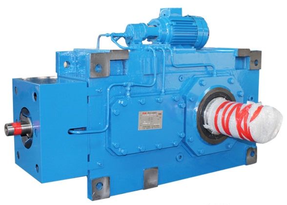


Bevel-helical speed reducers B2 ft HSS Fan with radial shaft seal Radial shaft se B2-FV-4B
In stock
SKU
B2-FV-4B
$282,857.14
Flender/Flender Gear Units/Bevel-helical speed reducers B2
nsion, such as the height of extrude, the depth of cutting, and the diameter of fillet, are all to be driven by parameters or expressions as well. 3.2.2 The fundamental geometric model of the case It includes the principal part
  of the case: the cube, th input and output axis with journals and keys, the positioning screw holes and so
  on. The involved dimensions of the above sketches and features are all given and to be assigned by the corresponding
  parameters directly. 3.2.3 The external embellish and its features Dimensions in this section are determined by designers. For the purpose of harmonize and artistic appearance, principle needs to be followed: to make sure that each fe atures size is consistent in the whole set. In another word, designers should try to make each dimension proportional to the same directions overall dimension (the length, width or height of the case). ( There are several bosses around th shafts, which are used for the shafts installation and removing. Originally there is an input axis and an output axis in both the front and the back side, but actually not all of them are necessary. In operation, ther efore, the redundant shaft can be removed. The sizes of these bosses may be settled according to shafts diameters and their distance, so that the corresponding dimensions should be assigned by equations containing diameters and distance. Thus, the bosses around the shafts are harmonized in all directions and uniformly distributed without any interference. ( If the two drive shafts are vertical rather than parallel, then the input axis should be installed on the left side, as well as boss around the axis. ( The oil galleries for lubrication are located in both the front and the back surface of the case and above the screw holes at the bottom. The galleries have to be interlinked with screw holes so that screws can normally cross the hole when fixing. With lubrication, the wear, heat, and possibility of seizure of g
| Model Type | Bevel-helical speed reducers B2 |
|---|---|
| Gear Type | Bevel Helical Gear |
| Weight (kg) | 13200.000000 |
| Ratio Range | 1 : 5…18 |
| Low Speed Output | Flanged shaft |
| Nominal Torque | 6200 Nm |
| Mounting Arrangements | Vertical mounting position |
| Manufacturer | Flender Limited. |
| Country of Manufacture | Cyprus |
| Data Sheet & Drawings | Bevel-helical speed reducers B2 ft HSS Fan with radial shaft seal Radial shaft se B2-FV-4B |
Related Products