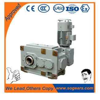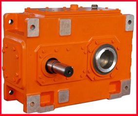
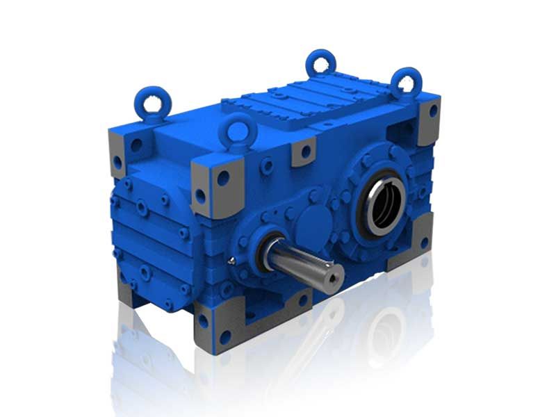
Flender/Flender Gear Units/Helical gear reducers H4
exchanger could be operated fullyautomati- cally in the same way as conventional equipment using refrigerants 1 and 2. Operation of the plate heat exchanger condenser presented no problems and yielded great- ertransfer capacitythan calculated without liquid banking,although it is not
  capable of achiev- ing the envisaged subcooling. In order to obtain minimum subcooling of 1 to 2 Kwith the cur-
  rent condenser design, separate subcooler has to be installed so as to enable bubble-free operation of the injection fittings. 2
  The plate heat exchan er evaporator also operated smoothly after solving the initial problems and yielded the calcuyated transfer capacity. However, better design could substantially reducethesizeofthis unit.Thiswouldalso result inasmallerrefrigerantcharge,asthisisessen- tially dependent on the evaporator capacity. Attention must be paid to uniform refrigerant dis- tribution in the evaporator. Given the current concept, the system operates satisfactorily in all load conditions with refri- gerant charge of 2.5 kg NH,. For practical urposes, the system cannot be operated with less than 1 Ksuction superheat- ing of the retigerant using the current evaporator design, because reduction in this super- heating is accompanied by increasingly unstable operating behaviour. The need to open the plate heat exchanger lead to an unavoidableinrush of water into the wel- ded refri erant-bearin plate compartment. This fact necessitated subsequent cleaning and drying oqthese weldej refrigerant chambers. The excellent efficiency of the oil separator and correctly dimensioned injector oil return sys- tem permitted trouble-free return transport of the oil from the evaporator to the compressor side, despite the virtual absence of an oilhefrigerant mixture. 2 Duration: 0 0 8 - 3 0 9 0ZH8C1 Subject: Collaborative project Reduction of CFC emissions in air-conditioning/ refrigeration Sub-Pro ect Evaluation of alternative cycles and fluids f
| Model Type | Helical gear reducers H4 |
|---|---|
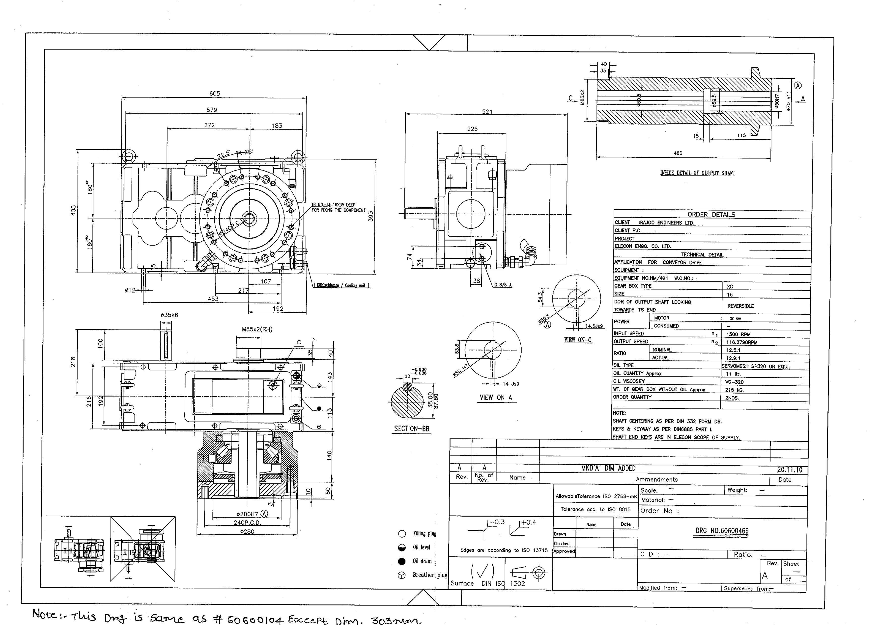
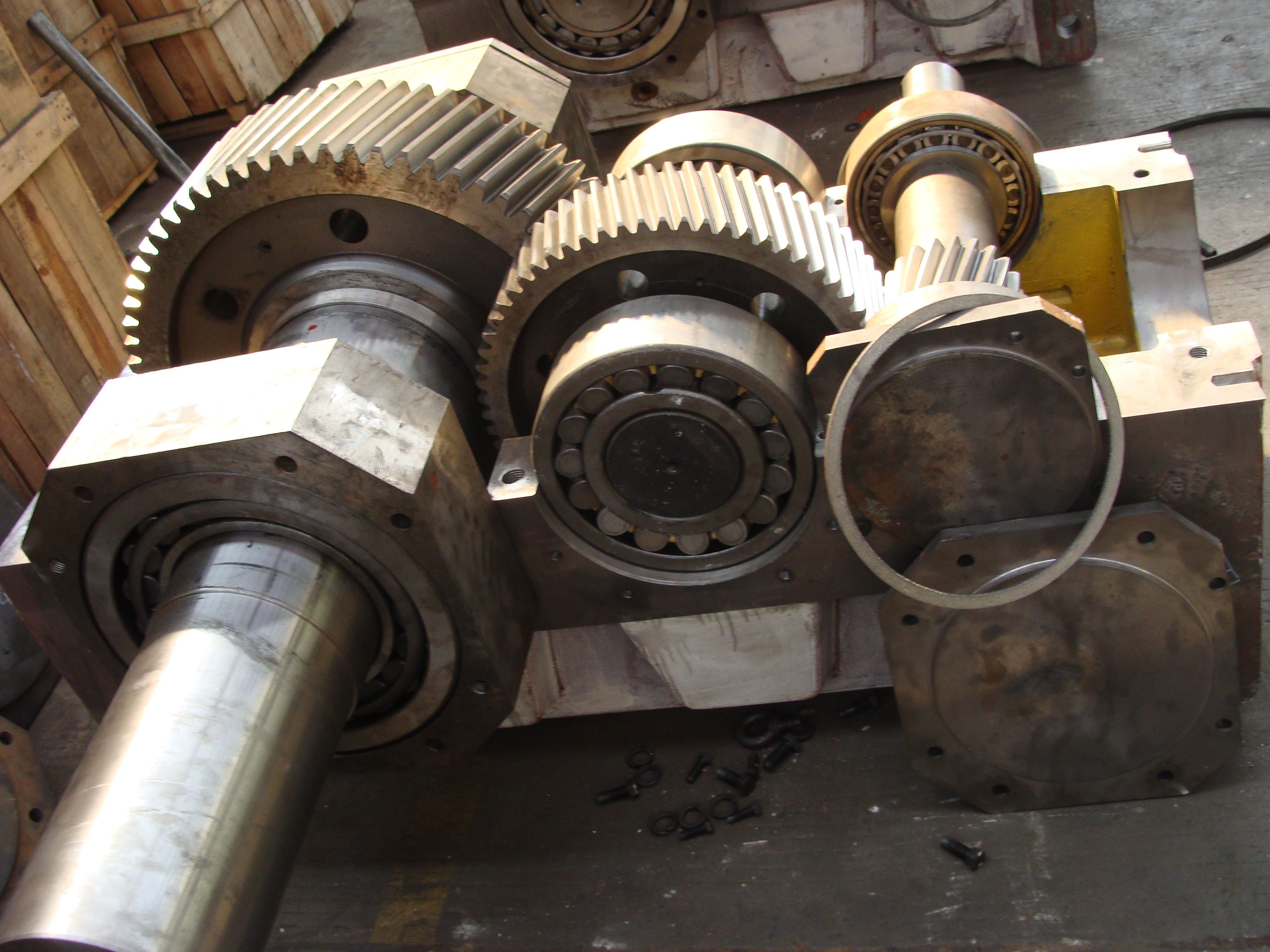
| Gear Type | Helical Gear |
| Weight (kg) | 2625.000000 |
| Ratio Range | 1 : 112…400 |
| Low Speed Output | Solid shaft with parallel key acc. to DIN 6885/1 |
| Nominal Torque | 173000 Nm |
| Mounting Arrangements | Horizontal mounting position |
| Manufacturer | A. Fried. Flender AG |
| Country of Manufacture | Germany |
| Data Sheet & Drawings | H4SH-16-C flender ie Helical gear reducers H4 |
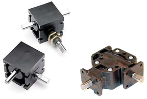
Related Products