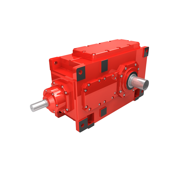
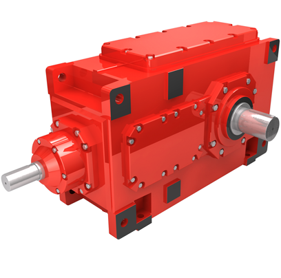
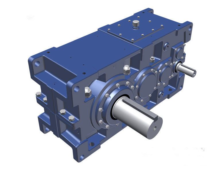

H4KV-10-C The individual power fractions PI PII Pn must n Helical gear box H4
In stock
SKU
H4KV-10-C
$7,821.43
Flender/Flender Gear Units/Helical gear box H4
ions of motion for the SDOF system are listed in Table 8.1. Transforming this differential equation into the frequency domain produces description of the dynamic behavior in the form of the compliance frequency response ( ) (Formula 8. which is
  caused by the complex ratios between dynamic displacement ( ) and dynamic force ( ). The compliance frequency response may
  be separated into amplitude and phase responses (Fig. 8.. The amplitude response represents compliance as function of frequency. The staticcompliance
  amplitude, .. the reciprocal of the static stiffness /, can be read off ata frequency 0 Hz. The system possesses its maximum compliance at resonance frequency . The phase response describes the time lag between the excitation force and the resulting displacement. Table 8.1 Differential equations in the frequency domain Designation Formula No. Time domain mxc_xkx dynxstat/C1 FstatFdyn (8. Frequency domainm^xj2c^xj ^xhi ejt^Fejt (8. Frequency responseGj xj Fj1 mj2cj (8.8.3 Dynamic Machine Behavior 3 Fig. 8.2 Compliance response principle Fig. 8.3 Amplitude and phase response f1frequency at phase angle 1 fRresonance frequency of the damped system fnresonance frequency of the undamped system at /C1 damping factor at /2mn Fig. 8.4 Nyquist plot3 8 Dynamics of Machine Tools form of representation, equivalent to the amplitude and phase responses, is the frequency response locus, or Nyquist plot, shown in Fig. 8.4. The distance from the origin of point on the Nyquist plot is the amount of compliance, while the rotation of this position vector in relation to the positive horizontal axis represents the phase. Because of passive system characteristics, there is always time lag between theforce and the displacement which requires negative phase values in the phaseresponse and frequency parameterization of the frequency response locus in theclockwise direction, .. in the mathematically negative direction of rotation. fundamental distinction is
| Model Type | Helical gear box H4 |
|---|---|
| Gear Type | Helical Gear |
| Weight (kg) | 365.000000 |
| Ratio Range | 1 : 125…450 |
| Low Speed Output | Hollow shaft with spline acc. to DIN 5480 |
| Nominal Torque | 44200 Nm |
| Mounting Arrangements | Vertical mounting position |
| Manufacturer | FLENDER GUSS GMBH |
| Country of Manufacture | Vietnam |
| Data Sheet & Drawings | H4KV-10-C The individual power fractions PI PII Pn must n Helical gear box H4 |
Related Products
