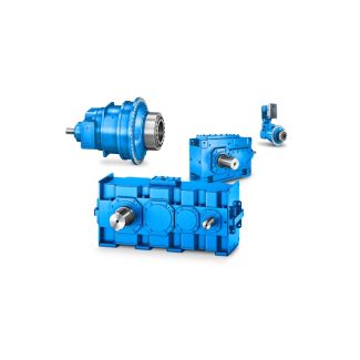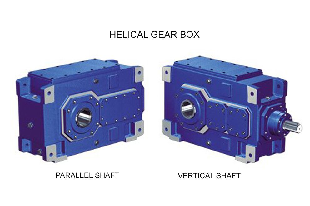

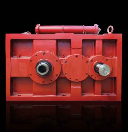
H4DV-8-C he Internet at httpsupport automation siemens com Helical gear unit H4
In stock
SKU
H4DV-8-C
$546,428.57
Flender/Flender Gear Units/Helical gear unit H4
in use for decades (Fig. 3.. The gear set is meshed and the contact pattern is determined at low Fig. 3.1 Flank modications using modied roll and helical motion8 3 Design torque. The contact pattern is shifted on the wheel
  by altering the pinion mounting distance () and the hypoid offset () while backlash is maintained constant byadjusting the mounting
  distance () of the wheel. In the US, the preferred symbols are (), (), (). 3.4.2 Displacements Caused by Tooth
  Forces The relative displacements of bevel gear set result from manufacturing tolerances on the housing and load-induced deections. The method used to calculate the toothforces on the teeth and bearings is described in Sect. 2.5. Beside deections of the tooth anks, these tooth forces deform the gear housing, the bearings and the gear bodies. These effects can be represented by relative displacements between the meshing tooth anks of the pinion and wheel. set of bevel gears with positive offset, comprising right-handed spiral wheel and left-handed spiral pinion, is shown in Fig. 3.2. The drawing shows the view along the wheel axis. The pinion tooth ank exerts force 2perpendicular to the surface of the tooth ank of the wheel, which counteracts with reactive force 1on the pinion. These forces do not necessarily act in the drawing plane, .. only the components which lie in the drawing plane are shown in Fig. 3.2. Force 1is split into two components Hand . In this conguration, the tooth forces reduce the hypoid offset and shift the pinion axially, thereby increasing its mountingdistance . tapered roller bearing in an -conguration is usually mounted behind the pinion such that the tooth forces press the pinion against the bearing.This mode of operation is termed drive, its opposite being coast (see Sect.2.2.4.5 ). Left hand spiral of wheel > 0: increased pinion mounting distance > 0: increased hypoid offset Right hand spiral of wheel > 0: increased pinion mounting distance < 0: increased hypoid o
| Model Type | Helical gear unit H4 |
|---|---|
| Gear Type | Helical Gear |
| Weight (kg) | 25500.000000 |
| Ratio Range | 1 : 125…450 |
| Low Speed Output | Hollow shaft with shrink disk |
| Nominal Torque | 27200 Nm |
| Mounting Arrangements | Vertical mounting position |
| Manufacturer | FLENDER GUSS GMBH |
| Country of Manufacture | Syria |
| Data Sheet & Drawings | H4DV-8-C he Internet at httpsupport automation siemens com Helical gear unit H4 |
Related Products