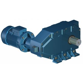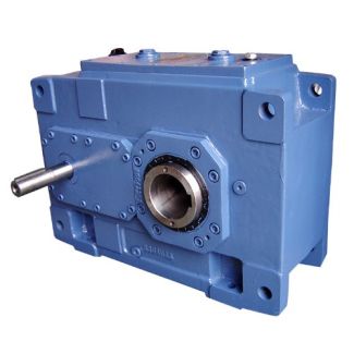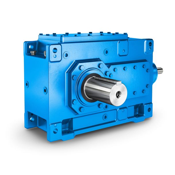

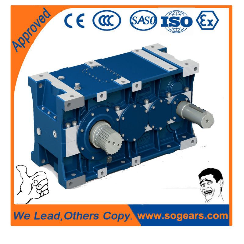

H4DV-24-C ystem etc Gear unitMounting and mounting position Helical gearboxes H4
In stock
SKU
H4DV-24-C
$173,571.43
Flender/Flender Gear Units/Helical gearboxes H4
ing edge,and is employed in bevel gear production as means to improve the running andnoise behavior of the gear set after hardening. In bevel gear lapping, the pinion and wheel are in mesh at low torque and high rotation speed
  such that abrasive contained in the lapping compound may removematerial from the tooth anks in the contact zone (Fig. 6..
  During the lapping6.6 Lapping 2 process, the contact zone is displaced by changing the relative positions of the pinion and
  wheel such that the complete tooth ank is lapped, possibly with increased material removal at selected points. Contact pressure between the meshing tooth anks is generated by an applied torque which acts with the sliding velocity to remove material. 6.6.3 Lapping Media 6.6.3.1 Lapping Compound The task of the lapping compound is to transport the lapping abrasive into the tooth contact zone and provide sufcient lubricating effect to prevent scufng of the gear set. The lapping compound should also retard settling of the lapping abrasive in the lapping medium tank, and still be easy to wash off the gear set after the lapping operation. Use of oil with thixotropic properties is recommended to keep the lapping abrasive in suspension. 6.6.3.2 Lapping Abrasive The lapping abrasive has decisive effect on material removal. In practice, silicon carbide has proved suitable because of hard, sharp-edged grains combined with its good cost-performance ratio. Less usual are lapping grains of aluminium oxide or boron nitride. The chosen grain size depends on the application. Basically, higher material removal can be obtained with large grain, but only at the expense of greater roughness on the tooth anks. grain size of 2 for module equal to 2.5 mm, or 2 for modules larger than 5 mm, is generally used in the automotive industry. The mass mix ratio of lapping compound to abrasive is usually 1 part of oil to 1.4 or 1.5 parts of abrasive. Fig. 6.3 Material removal by means of lapping2 6 Manufacturing Process 6.6.4
| Model Type | Helical gearboxes H4 |
|---|---|
| Gear Type | Helical Gear |
| Weight (kg) | 8100.000000 |
| Ratio Range | 1 : 112…400 |
| Low Speed Output | Hollow shaft with shrink disk |
| Nominal Torque | 725000 Nm |
| Mounting Arrangements | Vertical mounting position |
| Manufacturer | Beijing Flender |
| Country of Manufacture | China |
| Data Sheet & Drawings | H4DV-24-C ystem etc Gear unitMounting and mounting position Helical gearboxes H4 |
Related Products