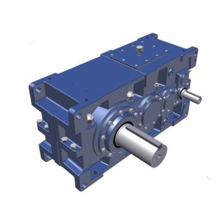
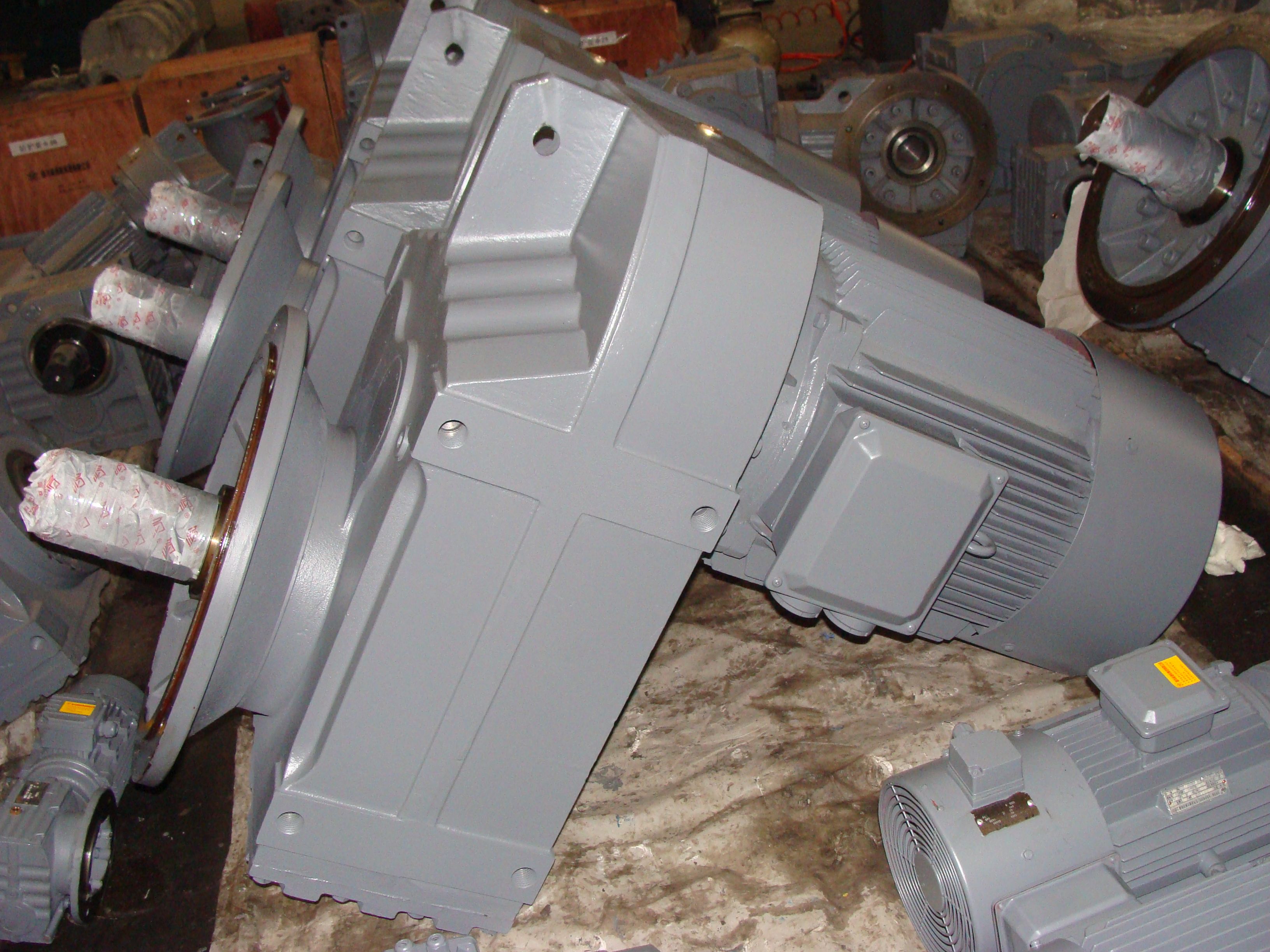
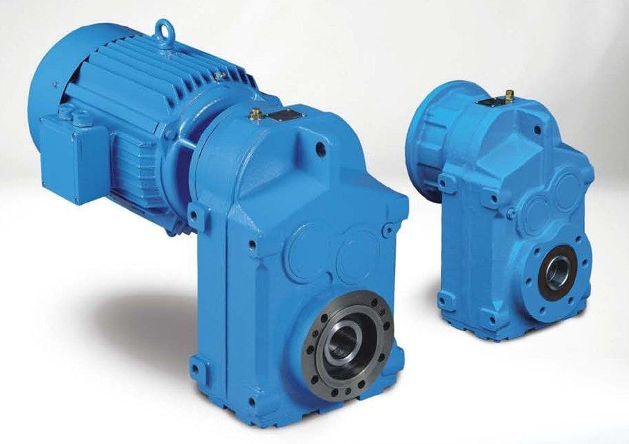
H4-SV-18B products and services For us highly qualified Helical gear units H4
In stock
SKU
H4-SV-18B
$56,250.00
Flender/Flender Gear Units/Helical gear units H4
ffset Fig. 3.1 Denition of horizontal and vertical displacements and V3.4 Displacement Behavior 8 If Fig. 3.2, the bevel gear set from Fig. 3.2 is shown in coast mode. In this case, the concave tooth ank of the wheel drives
  the convex tooth ank of the pinion. In the opposite direction of rotation, the convex pinion tooth ank drives the
  concave wheel tooth ank. The pinion exerts force 2on the tooth of the wheel, which reacts with force 1on the
  pinion. Force 1is split into components Hand FV. In coast mode, the tooth forces cause an increase in the hypoid offset and reduction in the mounting distance, .. an axial shift of the pinion towards the center of the gearbox. This axial displacement is harder to absorb for tapered roller bearing in -conguration behind the pinion, and there is risk that the bevel gear will jam if backlash is insufcient. In general terms, the displacement behavior for the drive and coast modes may be simplied by stating that in the drive mode the offset is reduced and the mounting distance increased, while in the coast mode the offset is increased and the mounting distance reduced. Fig. 3.2 Bevel gear set with positive offset in drive mode Fig. 3.2 Bevel gear set with positive offset in coast mode8 3 Design 3.4.3 Contact Pattern Displacement Figure 3.2 shows, on the tooth anks of the wheel, how the center of the contact pattern is displaced when varying values and . In each case, the arrows on the lines indicate the positive direction for the parameter change. It will be evident that on the drive side, .. the convex tooth ank on the wheel, with displacements <0 and >0 induced by the reactions on the teeth, the contact pattern moves towards heel and tip. On the coast side, with displacements >0 and <0, the contact pattern also moves towards heel, but with tendency towards tooth root. This phenomenon is typical of bevel gears which were cut with relatively large tool radius c0(Table 3.. The fat points in Fig. 3.2 show the way in which
| Model Type | Helical gear units H4 |
|---|---|
| Gear Type | Helical Gear |
| Weight (kg) | 2625.000000 |
| Ratio Range | 1 : 112…400 |
| Low Speed Output | Solid shaft with parallel key acc. to DIN 6885/1 |
| Nominal Torque | 240000 Nm |
| Mounting Arrangements | Vertical mounting position |
| Manufacturer | Flender GmbH |
| Country of Manufacture | South Korea |
| Data Sheet & Drawings | H4-SV-18B products and services For us highly qualified Helical gear units H4 |
Related Products