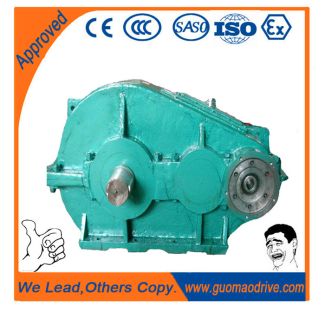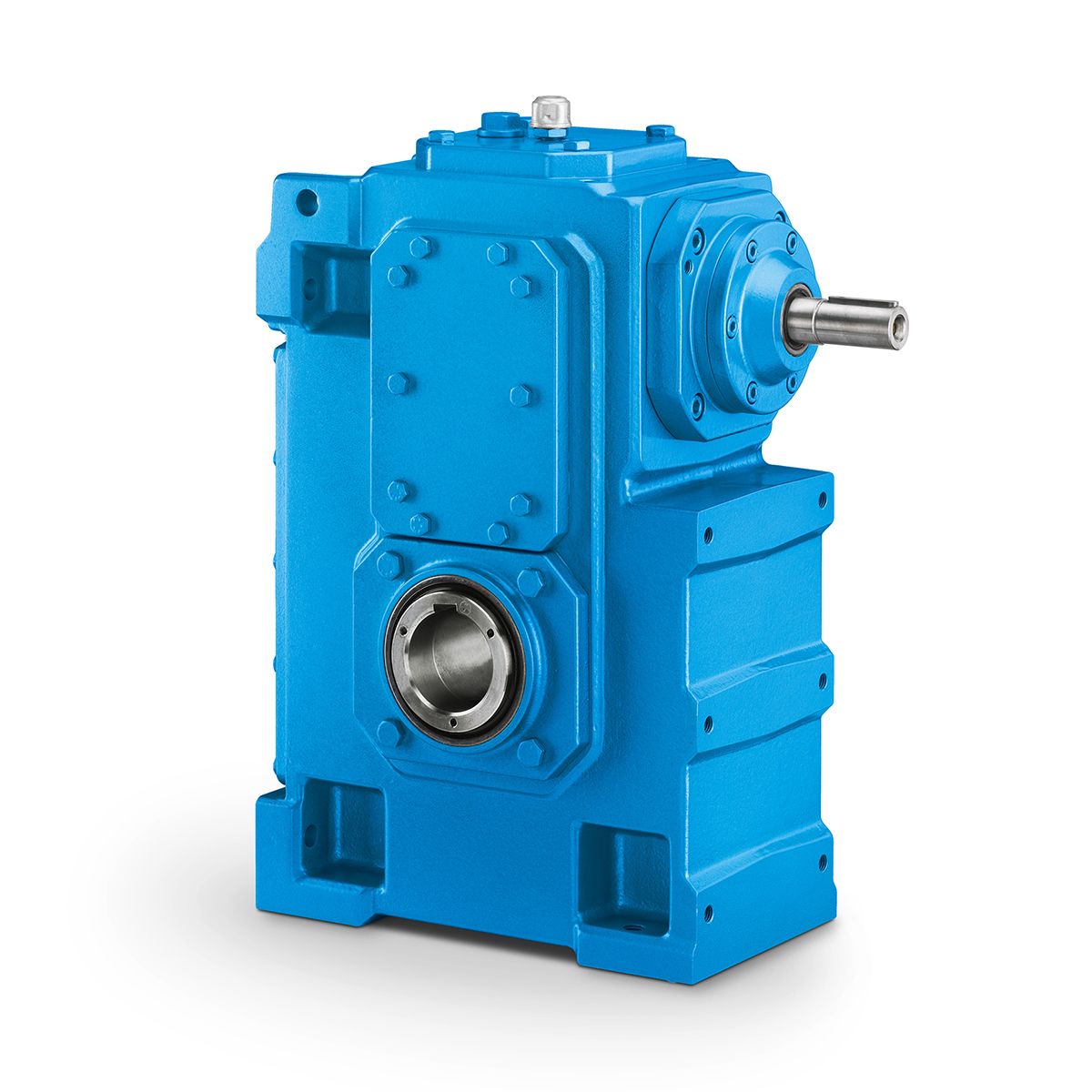
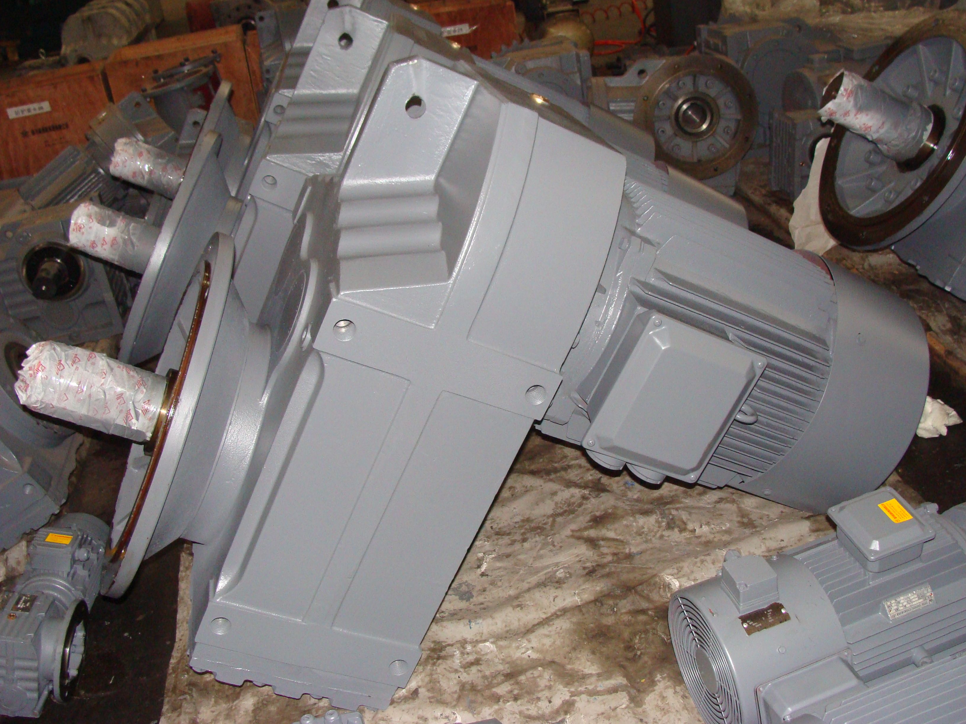
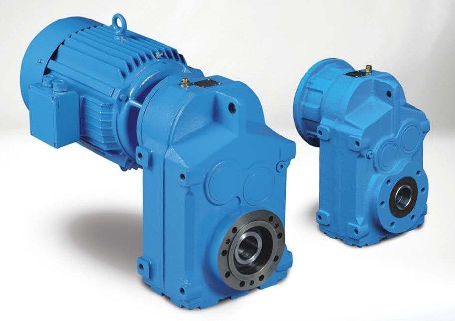
H4-SV-13-D Founding of Flender GmbH Flender GmbH Compete Helical gear reducer H4
In stock
SKU
H4-SV-13-D
$18,750.00
Flender/Flender Gear Units/Helical gear reducer H4
fe Switch Configuration Picture 2: MGS Unit 2 Trip Cutout Knife Switch Configuration Page 8 of 1 Malburg Generating Station Generator Protection Setting Review Picture 3: MGS Unit 3 Trip Cutout Knife Switch Configuration 2.2 Comparison of Enabled Protection Functions
  to Protection Criteria Document In addition to the physical trip testing, all protective relays were tested using secondary injection test
  set, the test results are included with this report in the file titled, IEM - Malburg -COV Generator Intertie Protection
  Testing Results April 2 .pdf . During the testing, relay settings were captured from each of the SEL relays for MGS Unit 1, 2, and 3. The settings are stored electronically and provided with this report in the file, Malburg Gen Stat ion Relays April 2.rdb. Each of the actual relay settings files were compared to the Protection Criteria Document to determine if the designed functionality existed within each of the relays. As found in the previous section, significant deviations from the design basis were present. Tables 4 , 5, 6, and 7 show summary of the differences found. Page 9 of 1 Malburg Generating Station Generator Protection Setting Review Table 4: MGS Unit 1,2, and 3 SEL- 3G Field Settings Vs. Design Criteria Table 5: MGS Unit 1,2, and 3 SEL- 3 Field Settings Vs. Design Criteria Table 6: MGS Unit 1,2, and 3 SEL- 3C Field Settings Vs. Design Criteria Table 7: MGS Unit 1,2, and 3 SEL- 4 Field Settings Vs. Design Criteria 2.3 Evaluation of Test Results and Physical Condition of Protective Relays All SEL protective relays were tested using secondary injection test set. All relays were found to be completely functional and all enabled elements performed within specification. From functional and hardware standpoint all relays were within specification and tolerances. Again, de tailed test results can be found in IEM - Malburg -COV Generator Intertie Protection Te
| Model Type | Helical gear reducer H4 |
|---|---|
| Gear Type | Helical Gear |
| Weight (kg) | 875.000000 |
| Ratio Range | 1 : 100…355 |
| Low Speed Output | Solid shaft with parallel key acc. to DIN 6885/1 |
| Nominal Torque | 90700 Nm |
| Mounting Arrangements | Vertical mounting position |
| Manufacturer | Flender Ibérica S.A. |
| Country of Manufacture | Portugal |
| Data Sheet & Drawings | H4-SV-13-D Founding of Flender GmbH Flender GmbH Compete Helical gear reducer H4 |
Related Products