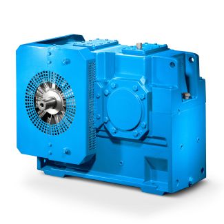


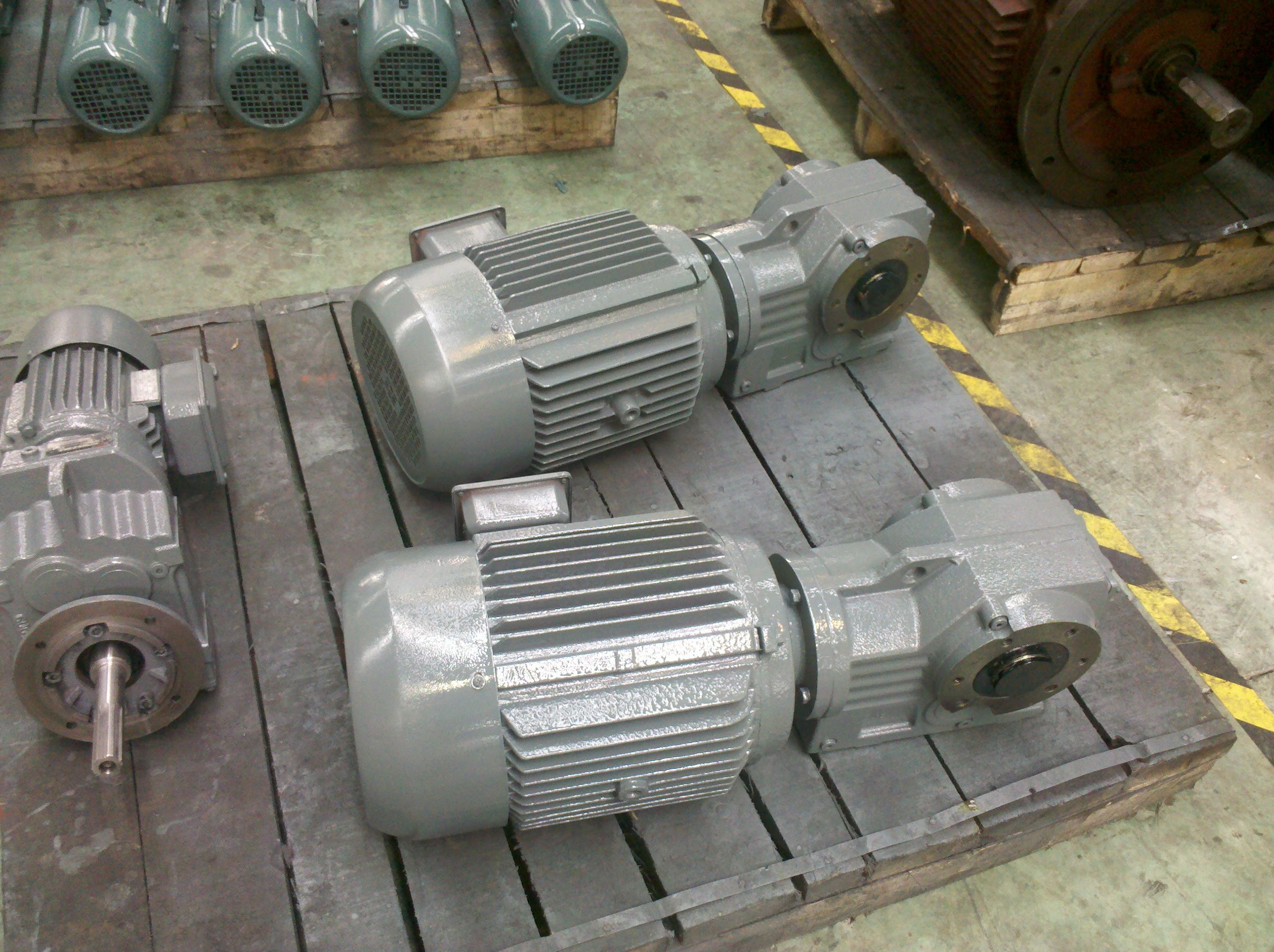
H4-KH16A ansion tank Forced lubrication on request Upright Helical gear Reduction Box H4
In stock
SKU
H4-KH16A
$56,250.00
Flender/Flender Gear Units/Helical gear Reduction Box H4
into shaft. 4. Smear shaft with copper slip or other anti-galling substance. 5. Slide coupling ( onto shaft (. 6. Ensure shaft sits down on shaft shoul der and the slide fit is neat fit .. coupling does not rock
  on shaft. 7. Fit locating/spigot plate ( to coupling ensure shaft end does not protrude past spigot plate face. 8.
  Fit 8.8 . bolts / spring washer and torque to recommend bolting torques given in service manual for the correct
  bolt size. Ensure bolt heads do not protrude outside spigot plate. 9. Remove coupling in reverse order. Bredgar Road, Gillingham, Kent, ME8 6PN Tel: 0 3 .Price: sales Siemens Flender mixertech.co.ukFax: 0 3 Internet : Germany mixertech.co.uk _______________________________________________________________________________ Bredgar Road, Gilli ngham, Kent, ME8 6PN Tel: 0 3 .Price: ales Siemens Flender mixertech.co.uk Fax: 0 3 Internet : Germany mixertech.co.uk ____________________________________________________________________ Bredgar Road, Gillingham, Kent, ME8 6PN Tel: 0 3 .Price: sales Siemens Flender mixertech.co.ukFax: 0 3 Internet : Germany mixertech.co.uk INSTALLATION OF BOTTOM STEADY BEARING OR SLAP RINGS bottom steady bearing (or slap ring) must be installed only after the drive assembly and lower agitator shaft, complete with impellers,has been assembled and firmly bolted inplace. Do not predetermine the exact bearinglocation from certified tank and mixer outlinedimension drawings. Th vertical centre line of the steady bearing must coincide with theshafts axis of rotation to minimise bearingpreload. This axis may not necessa rily be at the centre of the tank. The agitato shaft must be hand rotated (using input shaft coupling or motorfan with fixture attached to the shaft toscribe line on the tank bottom. The centreof this inscribed
| Model Type | Helical gear Reduction Box H4 |
|---|---|
| Gear Type | Helical Gear |
| Weight (kg) | 2625.000000 |
| Ratio Range | 1 : 112…400 |
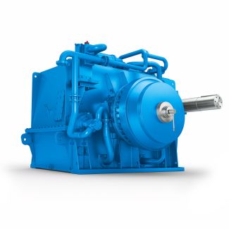
| Low Speed Output | Hollow shaft with spline acc. to DIN 5480 |
| Nominal Torque | 173000 Nm |
| Mounting Arrangements | Horizontal mounting position |
| Manufacturer | Siemens Industriegetriebe GmbH |
| Country of Manufacture | Moldova |
| Data Sheet & Drawings | H4-KH16A ansion tank Forced lubrication on request Upright Helical gear Reduction Box H4 |
Related Products