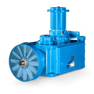

H4-HH28A ndependently of the color scheme ordered for the Helical gear reducers H4
In stock
SKU
H4-HH28A
$379,285.71
Flender/Flender Gear Units/Helical gear reducers H4
I 4 2 3,4 1 MR 2I 5 3 2,4 Manufacturer: Rossi - E0 9 MR 2I 4 7 2,1 9 MR 2I 4 7 1,3 1 MR 2I 5 1 2,3 1 MR 2I 5 2 1,3 1 MR
  2I 6 3 2,3 1 MR 2I 6 4 1 1 MR 2I 8 6 2,5 1 MR 2I 8
  7 2,1 1 MR 2I 1 1 2,4 1 MR 2I 1 1 1,3 2 MR 2I 1 2 2,3
  2 MR 2I 1 2 1 DOI: 1.1/ ,0 ( 7 1 1 MATEC Web of Conferences matec conf/2 2 MSE 2 Table 2. Examples of nominal torque capacities and high est gear ratio for three-stage gear reducer of different manufacturers. Axis height , mm Designation of gear unit Nominal output torque, TN, Nm Max gear ratio imax Manufacturer: SEW 9 2 1 1,0 9 3 2 1,8 1 4 3 1,8 1 5 4 1,8 Manufacturer: Siemens-Flender 9 D2 1 2,9 9 D3 2 1,7 Manufacturer: Nord - NORDBLOC 9 SK 2 1 3,9 9 SK 3 2 2,6 1 SK 4 3 3,5 1 SK 5 4 3,5 Manufacturer: Rossi - ES0 9 MR 3I 2 1 1 9 MR 3I 3 2 1 1 MR 3I 4 3 1 1 MR 3I 5 5 1 Manufacturer: Rossi - E0 9 MR 3I 4 8 9,8 9 MR 3I 4 9 7,4 1 MR 3I 5 1 1 1 MR 3I 5 2 1 1 MR 3I 6 3 1 1 MR 3I 6 4 1 1 MR 3I 8 6 1 1 MR 3I 8 9 1 1 MR 3I 1 1 1 1 MR 3I 1 1 1 2 MR 3I 1 2 1 2 MR 3I 1 3 1 DOI: 1.1/ ,0 ( 7 1 1 MATEC Web of Conferences matec conf/2 2 MSE 2 Fig. 5. Characteristic application areas of three-stage gear unit with larger torque capacity ( and with smaller torque capacity, but higher gear ratio (. Shaded area represents less expensive solution. Some large manufacturers are trying to cr eate so-called intermediate size of gear units and thus offer cheaper solution (Figure 6, Table . With this additional size, they increase the number of gear unit components they must produce (housings, gears, shafts, bearings, etc.), so this procedure can not be considered as favourable as the application of housing with two sets of gear pairs. Fig. 6. Schematic review of torque and gear ratio ar eas that are covered by certain sizes of gear reducers by introducing additional size. Table 3. Examples of providing additional size of two-stage gear
| Model Type | Helical gear reducers H4 |
|---|---|
| Gear Type | Helical Gear |
| Weight (kg) | 17700.000000 |
| Ratio Range | 1 : 112…400 |
| Low Speed Output | Hollow shaft with keyway acc. to DIN 6885/1 |
| Nominal Torque | 1400000 Nm |
| Mounting Arrangements | Horizontal mounting position |
| Manufacturer | FLENDER TÜBINGEN GMBH |
| Country of Manufacture | Qatar |
| Data Sheet & Drawings | H4-HH28A ndependently of the color scheme ordered for the Helical gear reducers H4 |
Related Products