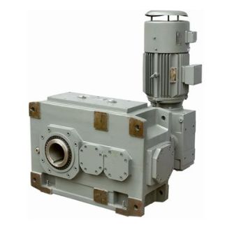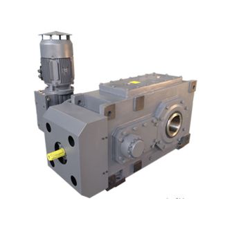
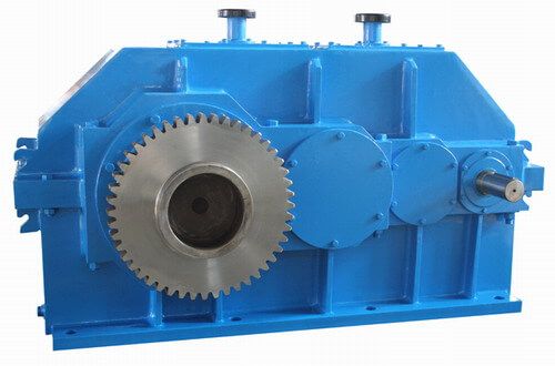
H4-HH-8B ilt within weeks using the Fast Track designator Helical gearbox H4
In stock
SKU
H4-HH-8B
$7,821.43
Flender/Flender Gear Units/Helical gearbox H4
hemically reductive metallising, except that externally electroless copper deposition is replaced by electrolytic cop- per-plating. The method, initial1 applied in laboratory-scale studies in connection with the use of catalyst system, included txe following process steps: 1. Drilling 2. Deburring 3.
  Oxidising pickl.ing 4. Reduction 5. Conditioning 6. Pickling 7. Redipping 8. Catalysing 9. Activation 1. Electroplating The PCBs metallised on
  laboratory scale using the processin yequence described were sub- jected to numerous tests, in order thoroughly to confirm reliability of
  the electrolytic ' method. At the same time, the individual process steps were tested and optimised using vari- ous chemicals. The influence of all the parameters mentioned on the quality of the PCBs was examined on more than 1,0 sample boards in each case, on the basis of the following criteria: - Adapter test, - Test of solderina behaviour. - Plating test, - Test of the holes in reflected and transmitted liaht. - Crack test, - Climate test, - Ageing test. Based on the test results, which were ultimately all positive, the decision was taken to consider the use of this electrolytic method on an industrial scale, articularly because initial cost calcu.la- tions had shown that this environmentally-friendly metiod also represented an economically attractive alternative to chemically reductive copper through-plating. However, the risk involved in directly converting the rocess to an industrial scale (scale-up of over ap eared to be too great, in view of tle dependence of the results on mass exchange prollems, .. geometric factors - particularly as some of the observations described had indicated this type of problem. For this reason, the project was expanded, in order to con- struct pilot plant and then convert this process step-by-step from the laboratory scale to industrial dimensions. ., . 8 3. Results 8,9 PCBs had been successfully metallised electroly
| Model Type | Helical gearbox H4 |
|---|---|
| Gear Type | Helical Gear |
| Weight (kg) | 365.000000 |
| Ratio Range | 1 : 125…450 |
| Low Speed Output | Hollow shaft with keyway acc. to DIN 6885/1 |
| Nominal Torque | 27200 Nm |
| Mounting Arrangements | Horizontal mounting position |
| Manufacturer | Flender Corporation |
| Country of Manufacture | Germany |
| Data Sheet & Drawings | H4-HH-8B ilt within weeks using the Fast Track designator Helical gearbox H4 |
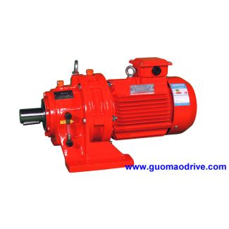
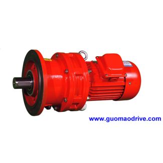
Related Products