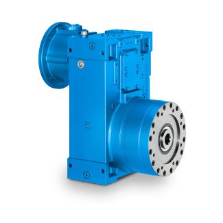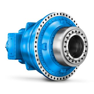
Helical gear boxes H4 Paper machines all types Pulper drives H4-FV-24B
In stock
SKU
H4-FV-24B
$173,571.43
Flender/Flender Gear Units/Helical gear boxes H4
lantern and fasten it by means of screws Pos.5 according to the prescribed torque, Table 1.2.5. Note: In case of installation of the drive outdoors or with higher degree of protection ( IP : Seal flange, screws Pos.5 and assembly
  plug Pos.5 and Pos.5 with sealant. Screw the grub screw Pos.5 onto the key Pos.5 until light resistance is felt,
  then unscrew half turn (wrench size SW1 see table 6.6.. To prevent the shafts turning insert socket spanner in threaded
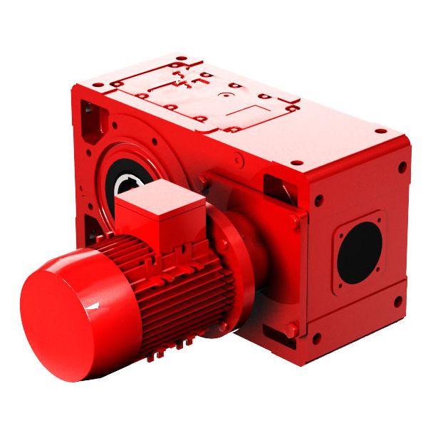
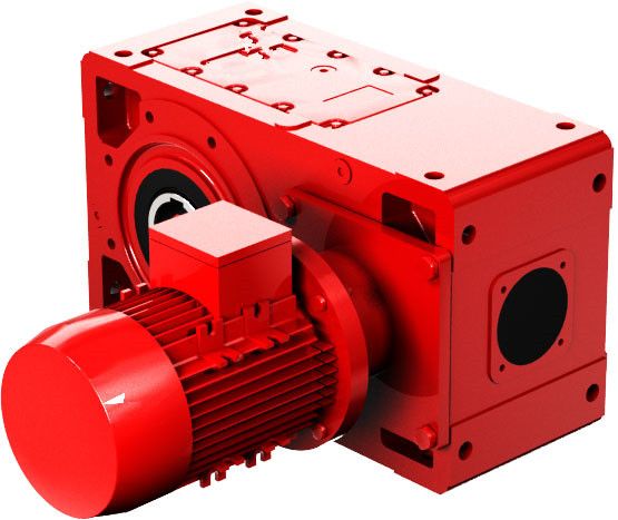
  pin, Pos.5, through bore for Pos.5. Tighten hexagon socket screw, Pos.5 with torque (torque and wrench size SW2 see table 6.6.. Tighten grub screw Pos.5. Cover mounting bores with plugs Pos.5 and Pos.5. 5 Mounting plug 5 Mounting plug5 Hexagon head screw 5 Grub screw 5 Parallel key5 Hexagon socket screw IEC B5 6 TA [Nm] 1 SW1 [mm] 2 SW2 [mm] 5 NEMA TC 5C1TC 1TC 2TCNEMA TC 5C1TC 1TC 2TC TA [Nm] 1 1 2 2 SW1 [mm] 2 2 3 3 SW2 [mm] 5 5 6 6 Table 6.6.2: Motor size 5 5 5 BA G2 EN 0.0 2 / 4.7 Motor base plate The motor bracket is designed for the mounting of an IEC-B3 bottom-mounted motor used primarily to power -belt drive. The motor must be set up in accordance with the makers operating instructions. Follow the relevant operating instructions for -belt drives, .. V5. Fit pulley wheels on to the drive shaft, Pos.5, in accordance with Section 6.5. Note: Incorrect belt tension results in belt breakages and damage to the bearing. For other types of drive, .. chain-type drive and the like, follow relevant operating instructions and/or makers information. Always fit suitable safety fixtures to cover the belt-, chain- or other open-type drive systems. After completion of mounting or adjustment work protect columns, Pos.5, and any other bright parts against corrosion as set out in Section 7.4 or with another suitable, permanent anti-corrosive agent. 6.7.1 IEC Motor frame size up to 1 Description of the assembly work Loosen screw (4x) Pos.5. Set height of motor plate, Pos.5, by evenly turning screws, Pos.5
| Model Type | Helical gear boxes H4 |
|---|---|
| Gear Type | Helical Gear |
| Weight (kg) | 8100.000000 |
| Ratio Range | 1 : 112…400 |
| Low Speed Output | Flanged shaft |
| Nominal Torque | 725000 Nm |
| Mounting Arrangements | Vertical mounting position |
| Manufacturer | FLENDER GRAFFENSTADEN |
| Country of Manufacture | Haiti |
| Data Sheet & Drawings | Helical gear boxes H4 Paper machines all types Pulper drives H4-FV-24B |
Related Products