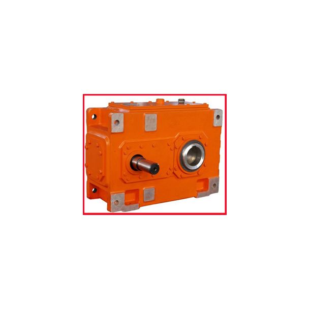
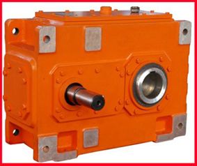


Flender/Flender Gear Units/Helical gear reducers H3
d)4 2 Fundamentals of Bevel Gears Determination of the pinion tooth face width (see Table 2.1 and Fig. 2. Whereas calculation of the pinion face width is trivial for non-offset bevel gears, its value being generally equal to that of
  the wheel, for hypoid gears it is function of the offset and can be calculated using three different methods (
  to ) as presented below.Table 2.1 (continued) Designation Formula No. Pinion offset angle in the face planeoarcsinacososina2 Rm2cosa2tz2cosa2/C1/C1 o(2. Face
  angle, pinion a1arcsin sin cosf2cosRcossinf2/C1(2. Root angle, pinion f1arcsin sin cosa2cosocossina2 (2. Addendum angle, pinion a1a1 (2. Dedendum angle, pinion f1f1 (2. Wheel face apex beyond the crossing point along wheel axistzF2tz2Rm2sina2ham2cosa2 sina2(2. Wheel root apex beyond the crossing point along wheel axistzR2tz2Rm2sinf2hfm2cosf2 sinf2(2. Pinion face apex beyond the crossing point along pinion axistzF1asinRcosf2tzR2sinf2c sina1(2. Pinion root apex beyond the crossing point along pinion axistzR1asinocosa2tzF2sina2c sinf1(2. Fig. 2.2 Pinion face width, inner and outer diameter [ ISO2 ]2.3 Bevel Gear Geometry Calculation 4 Table 2.1 Calculation of the pinion face width Designation Formula No. Face width in the pitch plane, pinionbp1 R2 e2a2 pq R2 i2a2 pq(2. Face width from calcula- tion point to front crown, pinionb1A R2 m2a2 pq R2 i2a2 pq(2. Formulae (2. to (2. apply to non-offset bevel gears: Face width, pinion b1b2 (2. Face width from calcula- tion point to outside (heel), pinionbe1cbe2b1 (2. Face width from calcula- tion point to inside (toe),pinionb i1b1be1 (2. The following formulae apply to hypoid gears. There are three possible methods: Method Auxiliary angle0arctansinmpcos2 ucos1cos2cosmp/C1/C1(2. Starting value for pinion face widthbreri1b2cos0 cos mp /C1(2. Pinion face width incre- ment along pinion axisbx1hmwsinR1 /C1/C1(2. Increment al
| Model Type | Helical gear reducers H3 |
|---|---|
| Gear Type | Helical Gear |
| Weight (kg) | 11880.000000 |
| Ratio Range | 1 : 22.4…90 |
| Low Speed Output | Solid shaft without parallel key |
| Nominal Torque | 640000 Nm |
| Mounting Arrangements | Horizontal mounting position |
| Manufacturer | Beijing Flender |
| Country of Manufacture | China |
| Data Sheet & Drawings | Helical gear reducers H3 n eupex 250 H3CH-23-C |
Related Products