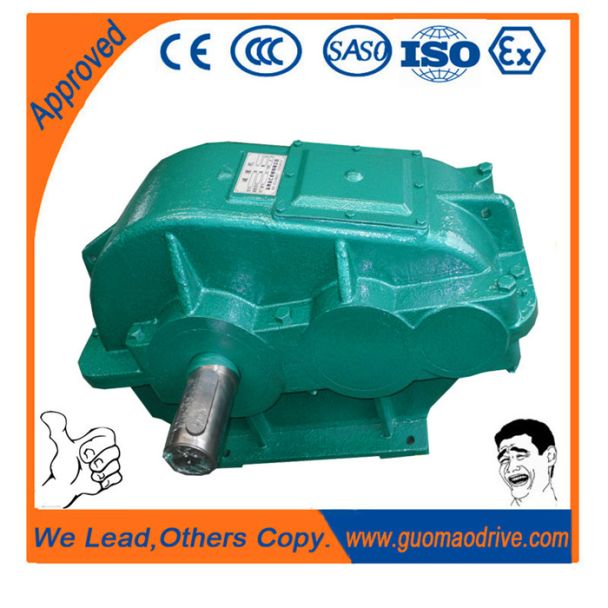
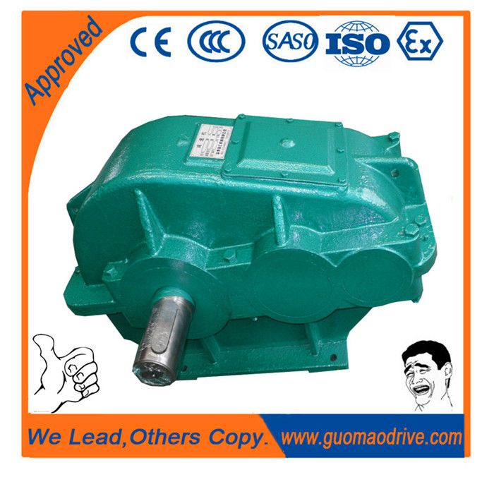
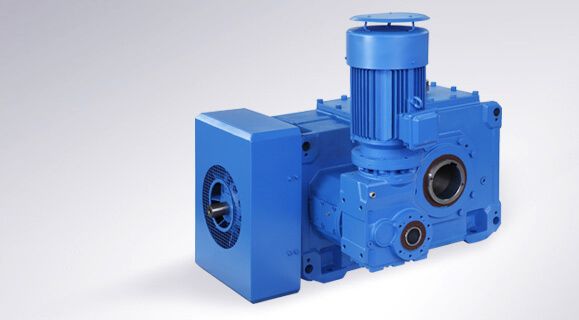
H3-VV11-B flender sip Helical speed reduction gearbox H3
In stock
SKU
H3-VV11-B
$30,000.00
Flender/Flender Gear Units/Helical speed reduction gearbox H3
cover at top (, view directed at drive end face (: Face 3 = right Face 6 = left -- 4A G_MD3_XX_0 G_MD3_XX_0A G8D8 G_MD3_XX_0A G8D8 G_MD3_XX_0A G8D8 G_MD3_XX_0G_MD3_XX_0B G_MD3_XX_0 G8 D8B G_MD3_XX_0 G8 D8B G_MD3_XX_0 G8 D8B G_MD3_XX_0 G8D8C
  G_MD3_XX_0 G8D8C G_MD3_XX_0G8D8C G_MD3_XX_0 G8 D8D G_MD3_XX_0 G8 D8D G_MD3_XX_0G8 D8D 1 G8D8E G_MD3_XX_0 G8D8 G_MD3_XX_0E 1G8D8 G_MD3_XX_0E $Backstop Siemens
  AG 2 Helical gear units horizontal mounting position Types H1, H2, H3 and H4 Article No. overview 4/2 Siemens MD
  3.1 2Selection and ordering data (continued) 7th position of the Article No. (continued) $BackstopDesigns , , on request. Data position of Article No. 1 to 6 7 8 1"-" and order code Article No. 2LP2 -.....-....-... Design variant (view directed at face 2, face 1 at bottom) Type H1.. H2.. H3.. H4.. --5 --6 --7 --8 G8 D8 G_MD3_XX_0F G8 D8F G_MD3_XX_0F 1 G8 D8 G_MD3_XX_0 G_MD3_XX_0G G_MD3_XX_0G_MD3_XX_0G G_MD3_XX_0H G_MD3_XX_0H G_MD3_XX_0H G_MD3_XX_0I G_MD3_XX_0I G_MD3_XX_0I Siemens AG 2 Helical gear units horizontal mounting position Types H1, H2, H3 and H4 Article No. overview 4/2 Siemens MD 3.1 2Selection and ordering data (continued) 8th to 1th position of the Article No. Data position of Article No. 1 to 6 7 8 1"-" and order code Article No. 2LP2 .-..-....-... Output shaft, gear unit size Output shaft Gear unit size Solid shaft () 5 2A 5 3A 5 4A 5 5A 5 6A 5 7A 5 8A 5 0B 5 1B 5 2B 5 3B 5 4B Hollow shaft with keyway () 5 3D 5 4D 5 5D 5 6D 5 7D 5 8D 5 0E 5 1E 5 2E 5 3E 5 4E Hollow shaft for shrink disk () 5 3G 5 4G 5 5G 5 6G 5 7G 5 8G 5 0H 5 1H 5 2H 5 3H 5 4H Siemens AG 2 Helical gear units horizontal mounting position Types H1, H2, H3 and H4 Article No. overview 4/2 Siemens MD 3.1 2Selection and ordering data (continued) 8th to 1th position of the Article No. (continued) Data position of Article No. 1 to 6 7 8 1"-" and order code Article No. 2LP2 .-..-....-... Output shaft, gear unit size Output shaft Gear unit size
| Model Type | Helical speed reduction gearbox H3 |
|---|---|
| Gear Type | Helical Gear |
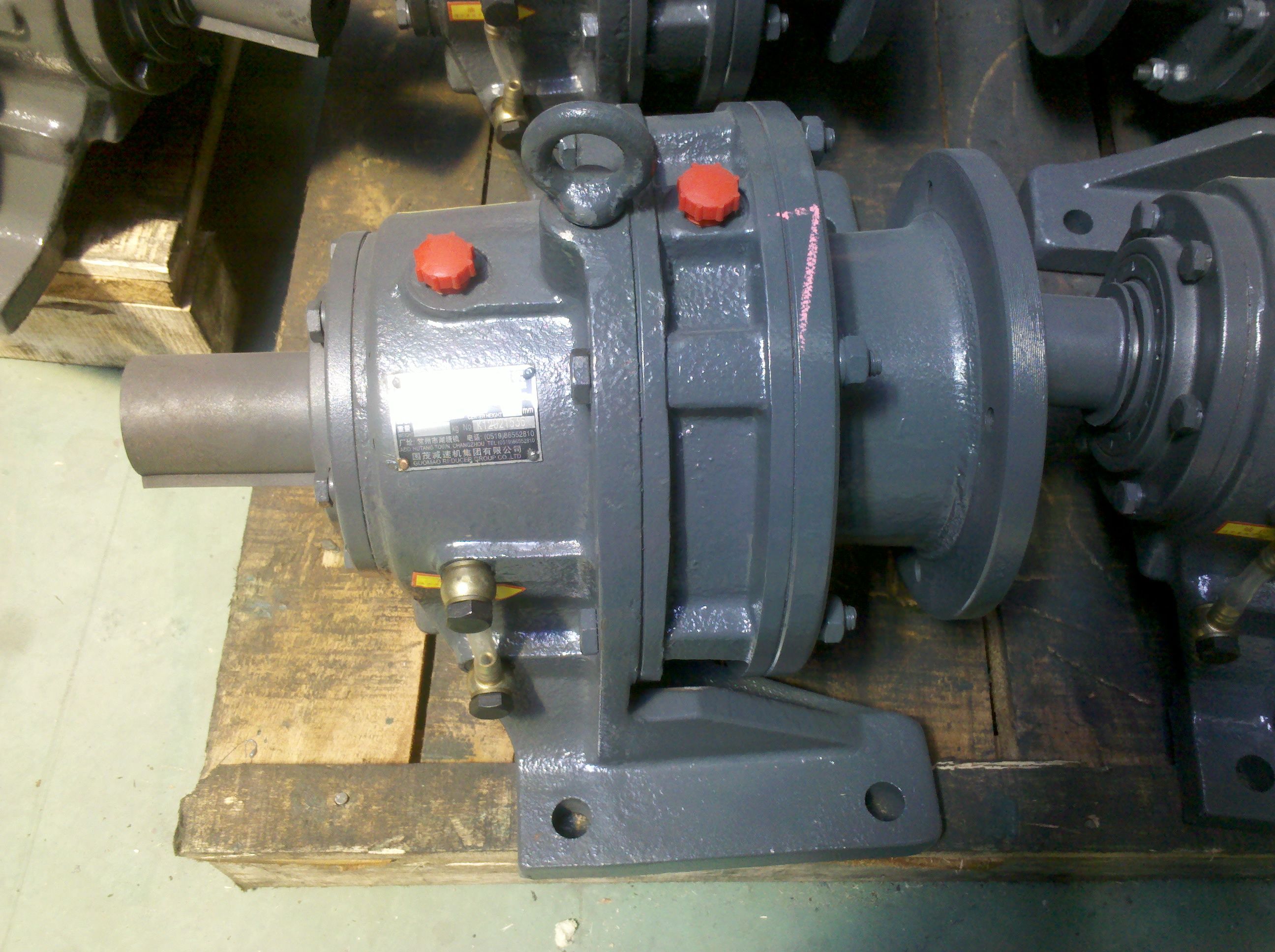
| Weight (kg) | 1400.000000 |
| Ratio Range | 1 : 25…90 |
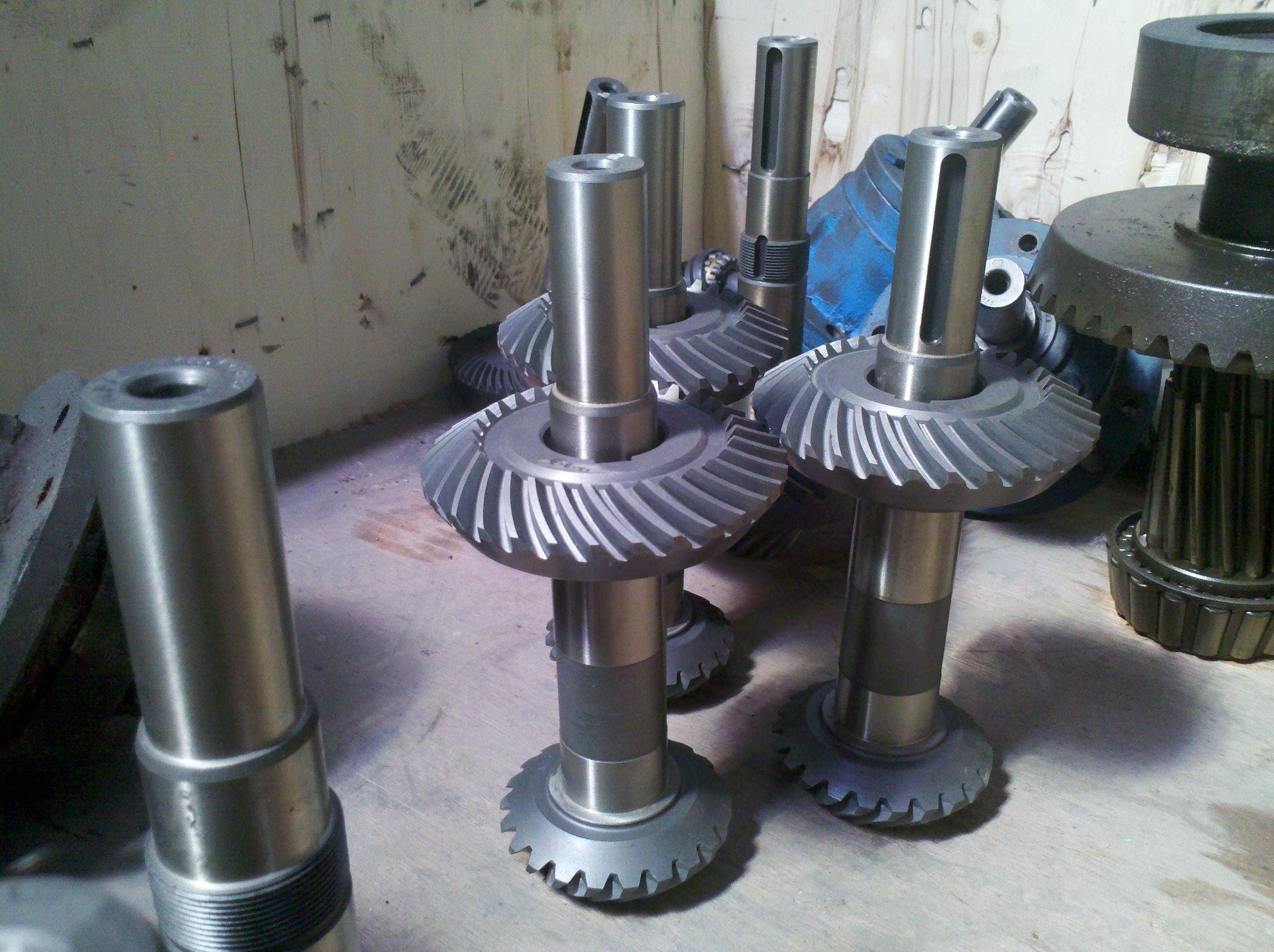
| Low Speed Output | Solid shaft with parallel key acc. to DIN 6885/1 with reinforced spigot |
| Nominal Torque | 61600 Nm |
| Mounting Arrangements | Vertical mounting position |
| Manufacturer | Flender Corporation |
| Country of Manufacture | Samoa |
| Data Sheet & Drawings | H3-VV11-B flender sip Helical speed reduction gearbox H3 |