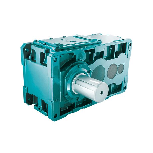
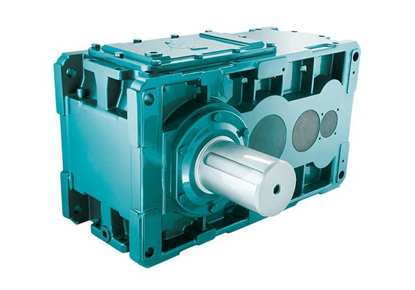
Flender/Flender Gear Units/Helical gear reducers H3
ccording to Table 4.2 ZMBmid-zone factor; converts curvature parameters to the decisive point of load application ZLSload sharing factor, which accounts for the number of simultaneously meshing teeth ZEelasticity factor, which accounts for material properties ZKbevel gear factor: ZK0.8 using
  [ ISO1 ] Method B1, whereas ZK1 using [ FVA4 ] (see Sect. 4.2.5.2 , Bevel slip factor ZS1, KAapplication
  factor, which accounts for additional external loads resulting from operating conditions Kvdynamic factor, which accounts for additional internal dynamic loads
  KHface load factor, which accounts for non-uniform load distribution over the face width KHload sharing factor, which accounts for non-uniform load sharing between meshing tooth pairs Load factors ,Kv,KHand Hare determined as in Tables 4.1,4.1,4.1,4.1,4.1, 4.1 Table 4.2 Calculation of mid-zone factor Designation Formula No. Mid-zone factorZMBtanvet dva1 dvb1/C1/C1 s F1 zv1"# /C1 dva2 dvb2/C1/C1 s F2 zv2"#vuut see Table 4.2 for auxiliary factors 1and 2(4.4.2 Load Capacity Calculation 1 Elasticity factor EMaterial-specic inuences on Hertzian contact stress, such as the modulus of elasticity and Poisson ratio, are considered by using the elasticity factor (Table 4.: Load sharing factor LSThe load sharing over several meshing tooth pairs is considered by the factor LSas calculated in Table 4.2. The distances fof contact lines for pitting load capacity are calculated in Table 4.2.Table 4.2 Factors to calculate mid-zone factor ZMFactor 1 F2 v0 2 0<<1 2vv /C2 Table 4.2 Calculation of the elasticity factor Designation Formula No. Elasticity factor ZE 1 E1 E2/C1/C1vuuut(4. For 1E2E and1: ZE 2 vuuutFor steel/steel pair: E1:8 (4. Table 4.2 Calculation of load sharing factor LS Designation Formula No. Load sharing factorZLS YLSp use LSformulae according to Table 4.1, but with fvalues according to Table 4.2(4. Table 4.2 Variable fto calculate th
| Model Type | Helical gear reducers H3 |
|---|---|
| Gear Type | Helical Gear |
| Weight (kg) | 625.000000 |
| Ratio Range | 1 : 31.5…112 |
| Low Speed Output | Solid shaft with parallel key acc. to DIN 6885/1 |
| Nominal Torque | 27200 Nm |
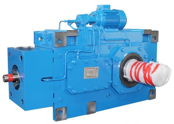
| Mounting Arrangements | Vertical mounting position |
| Manufacturer | Flender Guss Gmbh & Co. Kg |
| Country of Manufacture | Luxembourg |
| Data Sheet & Drawings | H3-SV8A flender china Helical gear reducers H3 |
Related Products