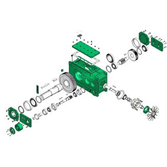

flender ag siemens H3-DH-14-D Helical gear boxes H3
In stock
SKU
H3-DH-14-D
$56,250.00
Flender/Flender Gear Units/Helical gear boxes H3
e transmission error and hence the effective total contact ratio can be determined with sufcient accuracy by means of tooth contact analysis(Fig. 5..Table 5.1 Effects of macro geometry design parameters on gear evaluation Increasing of:Having effects on: Contact ratio Tooth
  root load capacity Manufacturing costs Hypoid offset, + + Number of teeth, + Whole depth, + Module, mn + Spiral
  angle, + Pressure angle, + Tool radius, co + Face width, + + .2 Noise Excitation by Means of Gear
  Tooth Design 2 Location along path of contact Designation Point 1 to Point 5 Maximum contact of single tooth Point 2.1 to Point 4.1 Pitch Point 2 to Point 4 Effective tooth contact, dependent on load single tooth contact pitchMaximum total contact ratio effective tooth contact pitchEffective total contact ratio Fig. 5.4 Denition of the effective total contact ratio Fig. 5.5 Example of the dependence between transmission error and contact ratio2 5 Noise Behavior Gears with the same transmission ratio but differing tooth numbers were chosen for the curve shown in Fig. 5.5. The macro- and micro geometry were kept mainly constant for the calculation. There is good correlation between the total contact ratio and the transmission error. Hypoid Offset It is helpful to use the relative offset rel(see2.2.5.1 ) to calculate the offset in relation to noise excitation, since the offset must always be considered in proportion to the wheel diameter. As is evident from Fig. 5.6, the offset contributes only negligibly to the increase in contact ratio if the sum of the face widths and the sum of the spiral angles of pinion and wheel are kept constant. If the face width and the spiral angle solely of the wheel are kept constant, there is much more inuence. In this case, larger relative offset increases the face width and the spiral angle on the pinion, and hence the total contact ratio (Fig. 5.. Unlike gears without offset, longitudinal slid
| Model Type | Helical gear boxes H3 |
|---|---|
| Gear Type | Helical Gear |
| Weight (kg) | 2625.000000 |
| Ratio Range | 1 : 28…112 |
| Low Speed Output | Hollow shaft with shrink disk |
| Nominal Torque | 113000 Nm |
| Mounting Arrangements | Horizontal mounting position |
| Manufacturer | A. FRIEDR. FLENDER AG |
| Country of Manufacture | China |
| Data Sheet & Drawings | flender ag siemens H3-DH-14-D Helical gear boxes H3 |
Related Products