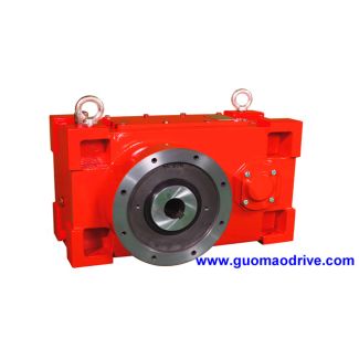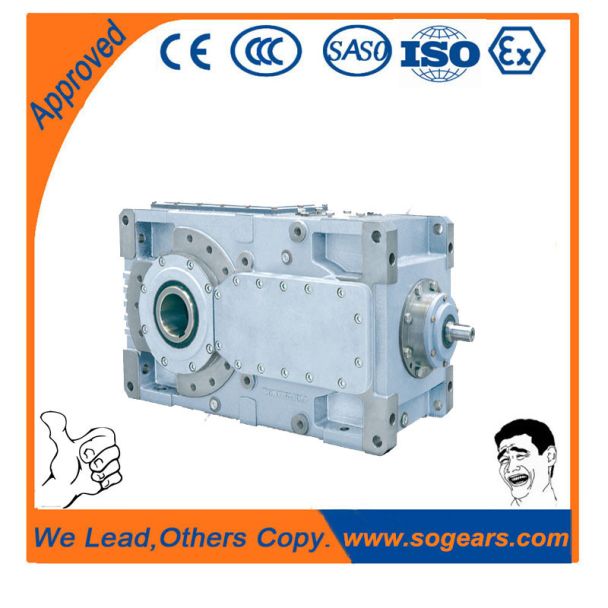

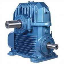
Helical speed reduction gearbox H3 flender industriegetriebe H3-CV5-B
In stock
SKU
H3-CV5-B
$6,857.14
Flender/Flender Gear Units/Helical speed reduction gearbox H3
dditionally determining the inuence of the change in stress state on the tooth face when compared to the center zone (plane stress state/plane deforma-tion state), expressed by the boundary stress reduction . Mirroring SS 1S1 4:3 Multiple mirroring is necessary
  for gear widths <6m mn. If this limit goes below signicantly, larger errors in the results must be anticipated. Form
  of the tooth facesWSt 1/C6:7/C1Stjj for the acute angled side of the tooth face for the obtuse angled side of
  the tooth face in radians4:3 Boundary stress reductionR/C3 tanh /C3 R1/C1 4:3 Influence functionSS1/C3/C3 /C3 /C1/C1/C1/C1/C1 S1/C3/C3 /C3 /C1 /C2/C3 /C1W/C1R 4:3 where: /C3V=mmnandR/C3R=mmn(see Fig. 4. Inuence numbers sijmay be determined using the stress reference value Nand function value : Influence numbers sijS/C1Nij sijdescribes the influence of the force Fnjexerted at point ion the stress at point i4:3 Stress reference value Nij6yFj/C1cos0 s2 Fni/C1b Nijstress reference value for tooth segment of width bat point ias result of loading at point j4:3 The stress reference value Nincludes the working point, lever arm , force application angle (see Fig. 4. of the single force applied at point , and the tooth thickness sFnin the normal section of the tooth root at each considered point . This value is calculated for tooth segment modeled as cantilevered beam.1 4 Load Capacity and Efciency Once the nominal stress curve has been calculated in three dimensions, the local stress (notch stress) on plane model is determined in second step. The stressconcentration due to the notch effect in the tooth root of gear is dependent on the llet notch parameter 2 Fn/sFnand on the lever arm of the load /sFn, and is thus different for each tooth segment of the numerical model. The stress-increasingeffect of the notch (in the llet) is expressed for each case (now beeing plane) bymeans of specic stress concentration factor . This is dened as the ratio of local stress to n
| Model Type | Helical speed reduction gearbox H3 |
|---|---|
| Gear Type | Helical Gear |
| Weight (kg) | 320.000000 |
| Ratio Range | 1 : 25…90 |
| Low Speed Output | Solid shaft without parallel key |
| Nominal Torque | – Nm |
| Mounting Arrangements | Vertical mounting position |
| Manufacturer | Siemens Flender |
| Country of Manufacture | Serbia |
| Data Sheet & Drawings | Helical speed reduction gearbox H3 flender industriegetriebe H3-CV5-B |
Related Products