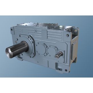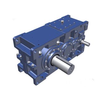

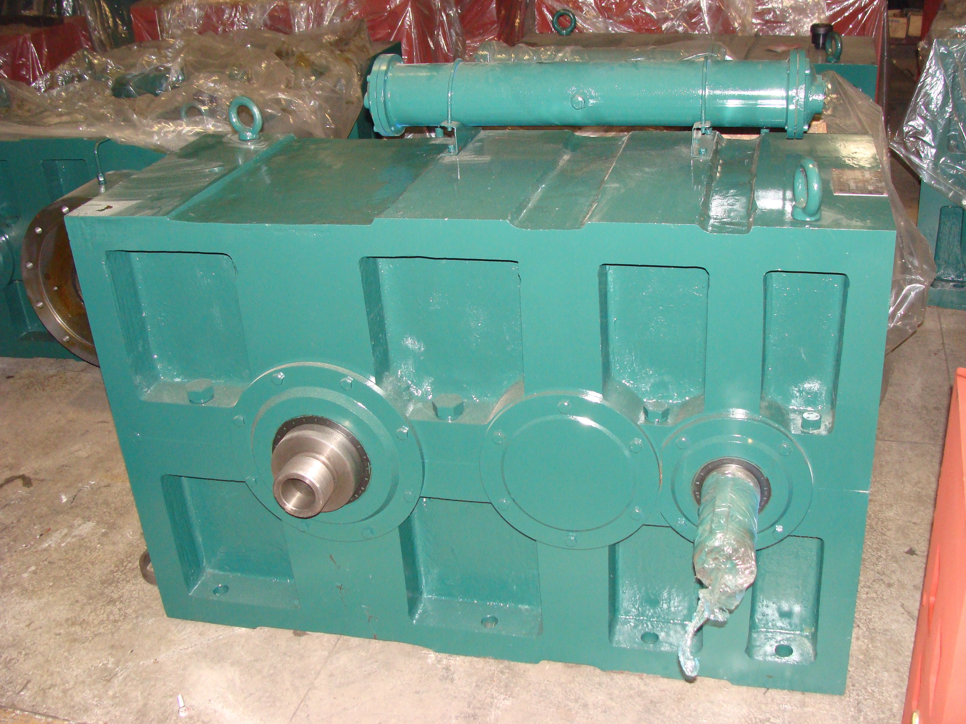
Helical gear reducer H3 flender fluid coupling catalogue H3-CV15-B
In stock
SKU
H3-CV15-B
$74,464.29
Flender/Flender Gear Units/Helical gear reducer H3
depth, of the kind generally used in passenger car rear axle units. The plotted transmission error values are intended as qualitative indication of the curves for the dependent variables. Other gears may exhibit different behaviors. As the results show, transmission
  error decreases with diminishing crowning or if the gear set has bias-in characteristic (see Sect. 3.4.3 ). The only changes
  made to generate the curves in Figs. 5.1 and5.1 were to the ease-off, all other parameters being kept constant. For
  the sake of simplicity, only circular crowning was used. Modern gear design and manufacturing offers number of additional possibilities allowing crowning not only in circular form, but with different curva- tures along the path of contact. The objective in crowning modications is to keep crowning in the contact area for low-load operation as small as possible, while signicantly increasing crowning in the outside areas to provide adequate displace- ment behavior. Modications for this purpose are possible on both the pinion and the wheel (see Sect. 3.4.5 and Fig. 3.. Fig. 5.1 Applied crowning for ground bevel gears compared to similarly loaded cylindrical gears5.2 Noise Excitation by Means of Gear Tooth Design 2 Fig. 5.1 Transmission error when bias varies Fig. 5.1 Transmission error when prole crowning is modied Fig. 5.1 Transmission error when lengthwise crowning is modied2 5 Noise Behavior 5.3 Noise Excitation Governed by Manufacturing 5.3.1 Inuence of Gear Deviations on Transmission Error Tooth ank topography of bevel gear teeth in the area of the contact pattern can be approximated by second order surface. The transmission error in the tooth meshing region is therefore close to parabola. If gear set is manufactured exactly such that there are deviations neither in macro- nor in micro-geometry, the resulting transmission error curve will be as shown in Fig. 5.2 where the pinion has 1 teeth. The corresponding order spectrum shows the amplitudes of the mesh h
| Model Type | Helical gear reducer H3 |
|---|---|
| Gear Type | Helical Gear |
| Weight (kg) | 3475.000000 |
| Ratio Range | 1 : 22.4…90 |
| Low Speed Output | Solid shaft without parallel key |
| Nominal Torque | 153000 Nm |
| Mounting Arrangements | Vertical mounting position |
| Manufacturer | flanders electric peru s a c |
| Country of Manufacture | China |
| Data Sheet & Drawings | Helical gear reducer H3 flender fluid coupling catalogue H3-CV15-B |
Related Products