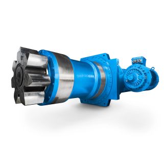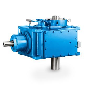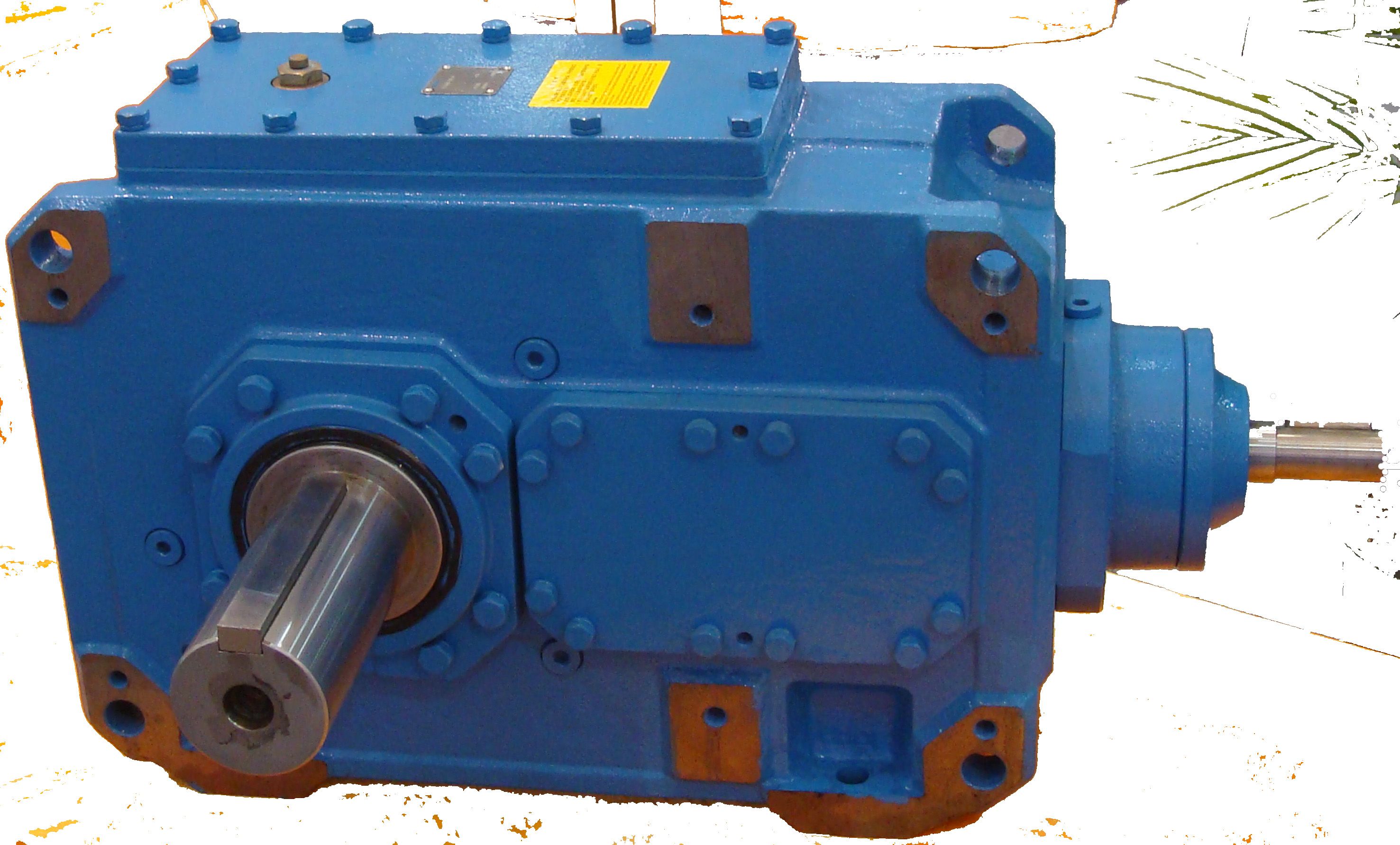


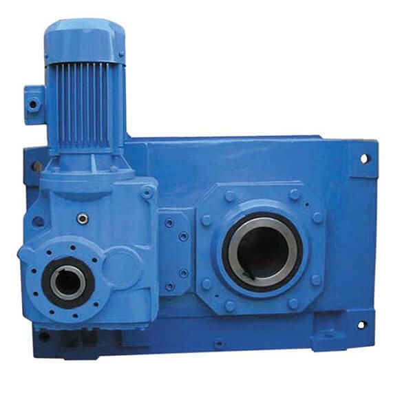
H2SV-6-C flender strasbourg Helical gear Reduction Box H2
In stock
SKU
H2SV-6-C
$7,607.14
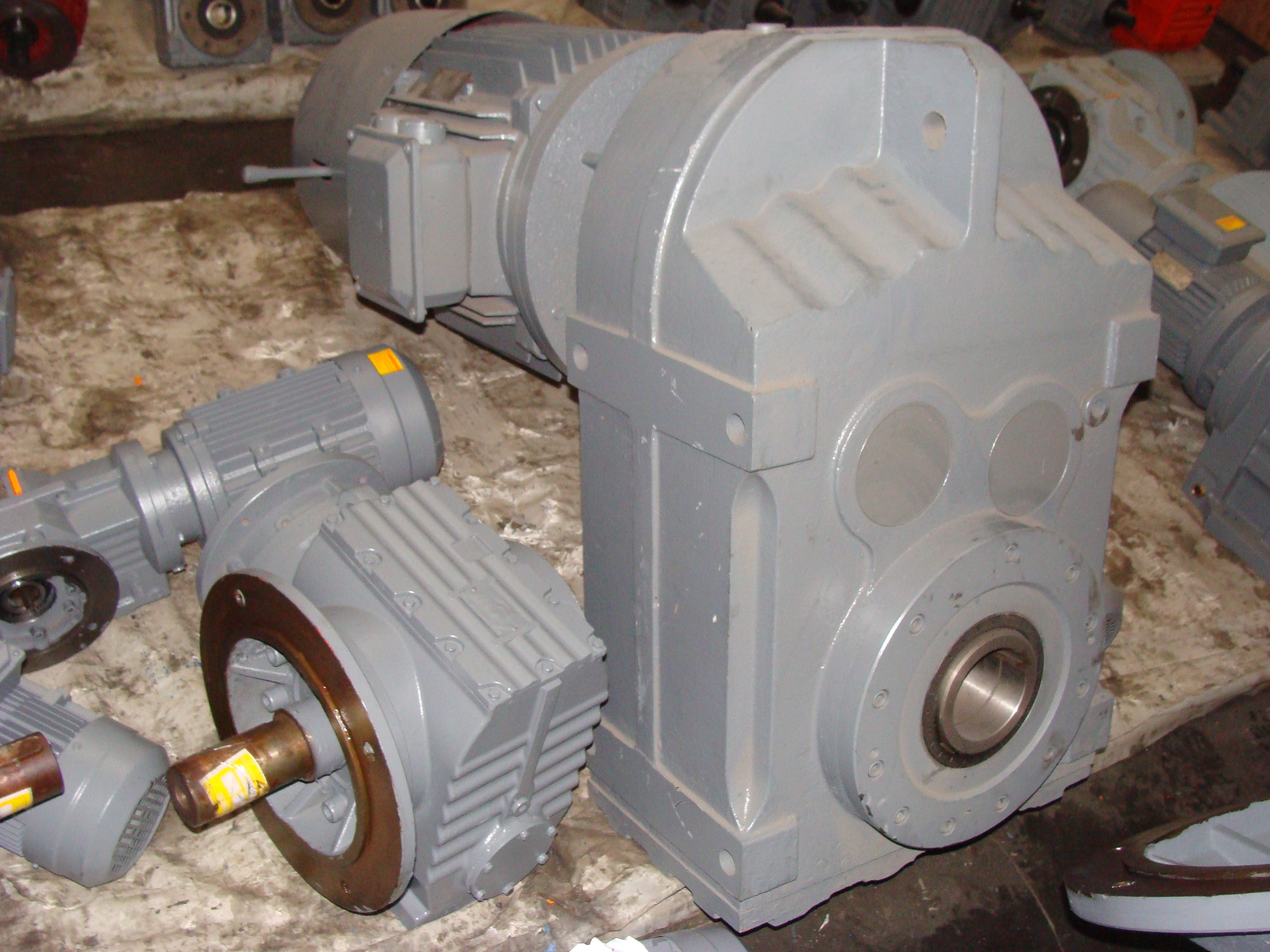
Flender/Flender Gear Units/Helical gear Reduction Box H2
0 0.0 0.0 0.0 0.0 0.0 1 0.0 0.0 0.0 0.0 0.0 0.0 0.0 0.0 0.0 0.0 1 0.0 0.0 0.0 0.0 0.0 0.0 0.0 0.0 0.0 0.0 1 0.0 0.0 0.0 0.0 0.0 0.0 0.0 0.0 0.0 0.0 1
  0.0 0.0 0.0 0.0 0.0 0.0 0.0 0.0 0.0 0.0 1 0.0 0.0 0.0 0.0 0.0 0.0 0.0 0.0 0.0
  0.0 2 0.0 0.0 0.0 0.0 0.0 0.0 0.0 0.0 0.0 0.0 2 0.0 0.0 0.0 0.0 0.0 0.0 0.0
  0.0 0.0 0.0 2 0.0 0.0 0.0 0.0 0.0 0.0 0.0 0.0 0.0 0.0 2 0.0 0.0 0.0 0.0 0.0 0.0 0.0 0.0 0.0 0.0 3 0.0 0.0 0.0 0.0 0.0 3 0.0 0.0 0.0 0.0 0.0 JL1 Types B2, B3, B4 Moments of inertia J1 Siemens AG 2 Design of the gear units Overview tables Types H1, H2, H3, H4 Actual ratio, gear unit sizes 5 to 5 3/6 Siemens MD 3.1 2Technical specifications Actual ratio for types H1, H2, H3, H4 Gear unit sizes iN 5 5 5 5 5 5 5 5 5 5 5 5 Type 1.1 1.1 1.0 1.0 1.0 1.1 H1.2 1.2 1.2 1.2 1.2 1.2 1.3 1.3 1.3 1.4 1.4 1.3 1.3 1.4 1.3 1.4 1.5 1.5 1.5 1.6 1.6 1.6 1.5 1.6 1.5 1.6 1.7 1.6 1.6 1.8 1.7 1.7 1.7 1.7 1.8 1.8 1.9 1.9 1.9 2 1.9 1.9 1.9 2.0 2.0 2.0 2.1 2.1 2.1 2.2 2.2 2.2 2.2 2.2 2.2 2.2 2.3 2.3 2.3 2.5 2.5 2.4 2.5 2.4 2.4 2.5 2.6 2.6 2.6 2.8 2.7 2.7 2.8 2.8 2.7 2.8 3 2.9 2.9 3.1 3.1 3.2 3.2 3.1 3.1 3.2 3.3 3.3 3.2 3.5 3.5 3.5 3.6 3.4 3.6 3.6 3.7 3.7 3.7 4 4.0 4.0 4.0 3.9 4.0 4.1 4.2 4.2 4.1 4.5 4.5 4.5 4.5 4.4 4.4 4.6 4.7 4.7 4.7 5 5.0 4.8 5.0 4.9 5.0 5.0 5.3 5.2 5.3 5.6 5.5 5.5 5.6 5.4 5.5 5.7 6 5.8 5.7 Siemens AG 2 Design of the gear units Overview tables Types H1, H2, H3, H4 Actual ratio, gear unit sizes 5 to 5 3/6 Siemens MD 3.1 2Technical specifications (continued) Actual ratio for types H1, H2, H3, H4 (continued) Gear unit sizes iN 5 5 5 5 5 5 5 5 5 5 5 5 Type 6.3 6.3 6.3 6.2 6.4 6.4 6.3 H2.1 7.1 7.0 6.9 7.1 7.1 7.0 8 7.8 8.1 7.8 7.9 8.1 8.1 7
| Model Type | Helical gear Reduction Box H2 |
|---|---|
| Gear Type | Helical Gear |
| Weight (kg) | 355.000000 |
| Ratio Range | 1 : 8…28 |
| Low Speed Output | Solid shaft with parallel key acc. to DIN 6885/1 |
| Nominal Torque | 14400 Nm |
| Mounting Arrangements | Vertical mounting position |
| Manufacturer | Flender (Australia) Pty. Ltd. |
| Country of Manufacture | China |
| Data Sheet & Drawings | H2SV-6-C flender strasbourg Helical gear Reduction Box H2 |
Related Products