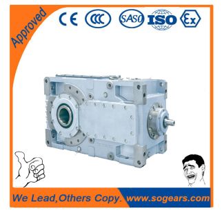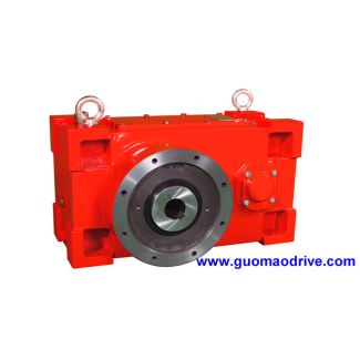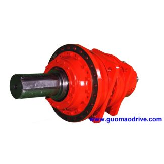


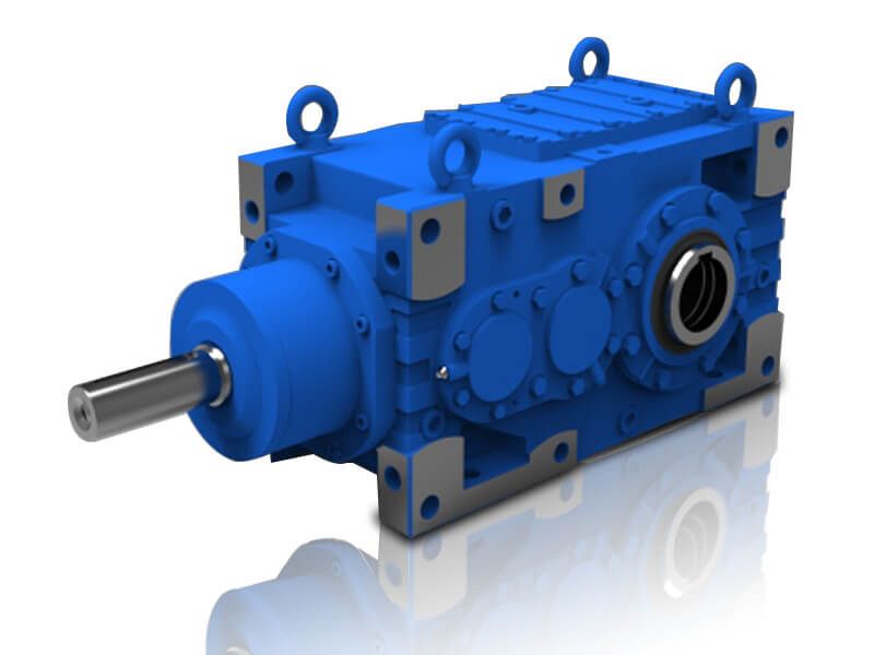
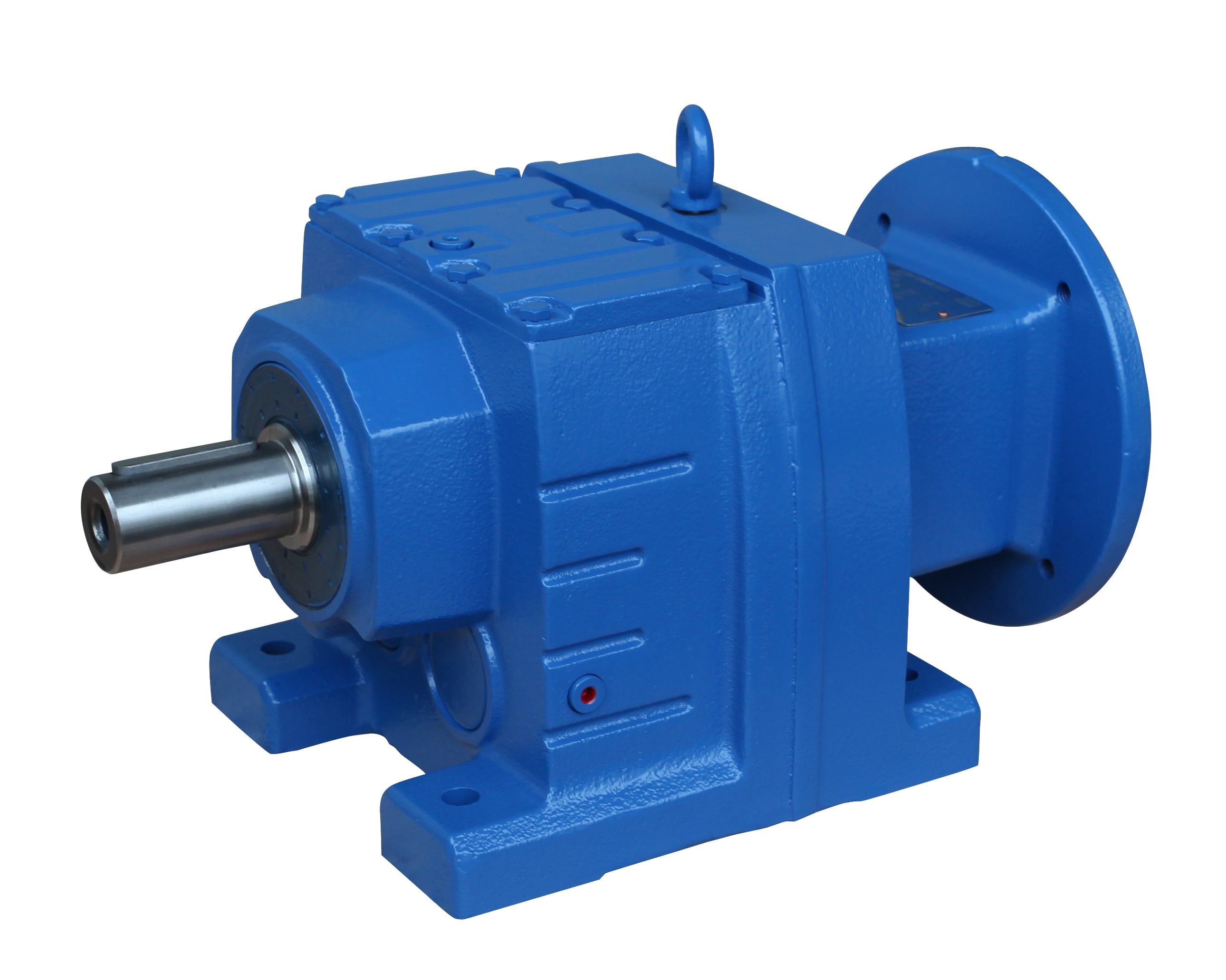
H2SH-9-C flender coupling usa Helical speed reduction gearboxes H2
In stock
SKU
H2SH-9-C
$17,785.71
Flender/Flender Gear Units/Helical speed reduction gearboxes H2
)2r2K /H2sin2ccosc/H1Ksin3c/H1Kr msin2ccos 2c/H2 Differentiating Eq. ( .. cand putting it equal to zero dFr dc/H1/H1 sin 2c/H1Kcos 2c/H1Kr mcoscsin 2c/H1Kr msinccos 2c /H1Kcos 2c/H1K2sin 2c/H1K2r msincsin 2c/H1K2r mcosccos 2c /H1Kr msin3c/H1Kr msin 2ccosc/H1K2r msin2ccosc /H1K2r2 m2sin2csin 2c/H1K2r2 m2sin 2ccos
  2c/H1 On simplication and rearranging the terms, /H2Kr msinc/H1K2r mcosc/H1K2r2 m2sin 2c/H1K/H2cos 2c /H1/H2Kr mcosc/H1K2r msinc/H1K2r2 m2sin2c/H1K2/H1/H2sin 2c ( /H1Kr
  /H2Kcosc/H1sinc/H2sin2c/H1 The minimum and maximum values of crank angles ( minandmax) satisfying Eq. ( have been obtained by developing suitable
  program and setting the specic values ofr,, and . These are summarized in Table 5. Once we know the values of crank angles, minandmaxfrom Table 5, two values of ( Fr)maxcan be determined from Eq. ( and the maximum value of Fris selected for balancing the rotating component. 8 DattaTable 5 Minimum and Maximum Crank Angles for ( Fr)max Minimum and maximum crank angles ( ) Level of Pitman length, (cm) cutter-bar 5 6 7 8 9 1 Crank from crank radius center, , min max min max min max min max min max min max (cm) (cm) ( )( )( )( )( )( )( )( )( )( )( )( ) 3.8 3 2.8 1.9 2.6 1.5 1.1 1.7 1.5 1.7 1.5 1.2 1.0 1.1 (0.(0.(0.(0.(0.(0. 3 3.3 1.1 2.3 1.3 2.2 1.7 1.1 1.2 1.8 1.4 1.0 1.0 (0.(0.(0.(0.(0. (0. 4 3.3 1.2 2.1 1.5 2.3 1.9 2.8 1.9 1.2 1.7 1.1 1.0 (1.(0.(0.(0.(0.(0. 4.1 3 2.1 1.8 2.3 1.4 1.3 1.6 1.7 1.6 1.7 1.1 1.1 1.0 3 3.6 1.1 2.6 1.2 2.4 1.6 1.3 1.1 1.0 1.9 1.2 1.9 3.6 1.2 2.4 1.4 2.5 1.9 2.0 1.8 1.3 1.6 1.2 1.9 4.4 3 2.4 1.6 2.2 1.2 1.5 1.4 1.8 1.5 1.8 1.0 1.2 1.9 3 3.9 1.0 2.9 1.1 2.6 1.5 1.5 1.0 1.1 1.2 1.3 1.8 4 3.8 1.2 2.6 1.3 2.8 1.8 2.2 1.7 1.5 1.5 1.4 1.8 4.7 3 2.7 1.5 2.5 1.1 1.7 1.3 1.0 1.3 1.9 1.9 1.3 1.8 3 3.2 1.9 2.1 1.0 2.9 1.4 1.7 1.9 1.3 1.1 1.4 1.7 4 3.1 1.2 2.9 1.3 2.0 1.7 2.4 1.6 1.7 1.4 1.5 1.7 5.0 3 2.1 1.4 2.7 1.0 1.0 1.2 1.2 1.2 1.1 1.8 1.5 1.7 3 3.5 1.9 2.4 1.9 2.1 1.3 1.9 1.8 1.5 1.0 1.
| Model Type | Helical speed reduction gearboxes H2 |
|---|---|
| Gear Type | Helical Gear |
| Weight (kg) | 830.000000 |
| Ratio Range | 1 : 6.3…22.4 |
| Low Speed Output | Solid shaft with parallel key acc. to DIN 6885/1 |
| Nominal Torque | 33700 Nm |
| Mounting Arrangements | Horizontal mounting position |
| Manufacturer | Flender (Australia) Pty. Ltd. |
| Country of Manufacture | Germany |
| Data Sheet & Drawings | H2SH-9-C flender coupling usa Helical speed reduction gearboxes H2 |
Related Products