
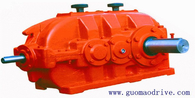
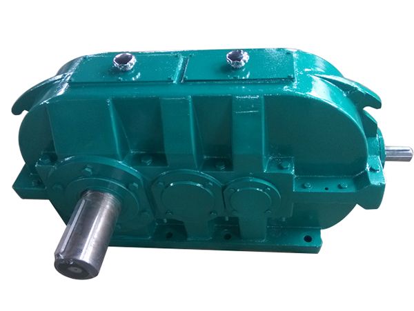

Flender/Flender Gear Units/Helical gear reducers H2
2 3 G4G4D 2 3 G7 d2D 3 k2n Shaft seals, see page 1/2 onwards. For details on the shafts, see Chapter 9 . Cooling options, see page 1/1 onwards.Approximate values; exact data acc. to order-related documentation. Without oil filling.
  Shaft variant designed to withstand axia forces (including those caused by weight of gear unit) on request. Shaft version with
  reinforced bearing, see page 9/7. Flender GmbH 2NER GROUP CO.,LIMITED Germany sogears HB series gearbox 7/1 Flender MD 2.1 2Bevel
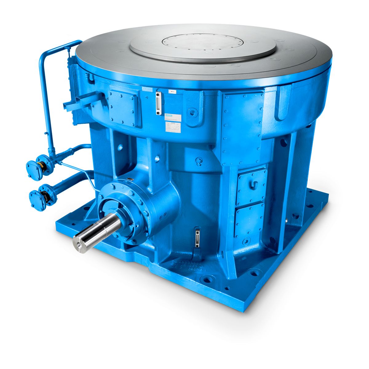
  helical gear units vertical mounting position Type B3 Gear unit dimensions, three-st age, gear unit sizes 1 to 2 Selection and ordering data Dimensions in mm Gear unit sizeHigh speed shaft (HSS) Fan iN d1 l1 l3 G1 G3 A1 B1 d6 G6 1 1.5 - 4 1 n6 2 2 1 1 On request 5 - 7 1 m6 2 1 2 1 - 5 1 n6 2 2 1 1 5 - 8 1 m6 2 1 2 1.5 - 4 1 n6 2 2 1 1 5 - 7 1 m6 2 1 2 1 - 5 1 n6 2 2 1 2 5 - 8 1 m6 2 1 2 2 - 4 1 n6 2 2 2 2 5 - 7 1 n6 2 1 2 2.4 - 5 1 n6 2 2 2 2 5 - 8 1 n6 2 1 Gear unit size e2 e3 f2 f3 h2 m1 m2 n1 n2 p 1 2 1 9 2 9 5 4 5 On request3 3 1 9 On request5 7 6 On request 2 2 1 9 2 1 6 4 5 3 3 1 9 5 7 6 2 2 1 1 2 1 6 4 6 4 3 1 1 5 7 7 2 2 1 1 2 1 7 4 6 4 3 2 1 6 7 7 2 On request 2B3. Dip lubrication 2LP3.-...1-.... Air intakeFan PumpG_MD2_EN_0s A1 A1 p2c m2 bd1d6 h2 f2 f3h hl1 G1 B1 LSS n2 n1l3 e2m1e3 G6~3 G3E G_MD2_XX_0BAB3. Forced lubrication by motor pump 2LP3.-...1-.... Shaft seals, see page 1/2 onwards. For details on the shafts, see Chapter 9 .Free space for pump, pipes and cov er; please contact us for exact dimensions, if applicable. Flender GmbH 2NER GROUP CO.,LIMITED Germany sogears HB series gearbox 7/1 Flender MD 2.1 2 7Bevel helical gear units vertical mounting position Type B3 Gear unit dimensions, three-st age, gear unit sizes 1 to 2 Selection and ordering data (continued) Low speed shaft (LSS) Oil quantity B3. Dip lubri- cationOil quantity B3. Forced lubrica- tionWeight B3.V1th to 1th position of Article No. and Article No. supplement, for 1th to 1th posit
| Model Type | Helical gear reducers H2 |
|---|---|
| Gear Type | Helical Gear |
| Weight (kg) | 590.000000 |
| Ratio Range | 1 : 8…28 |
| Low Speed Output | Solid shaft with parallel key acc. to DIN 6885/1 with reinforced spigot |
| Nominal Torque | 25600 Nm |
| Mounting Arrangements | Vertical mounting position |
| Manufacturer | FLENDER GUSS GMBH |
| Country of Manufacture | Austria |
| Data Sheet & Drawings | H2-VV8A flenders Helical gear reducers H2 |
Related Products


