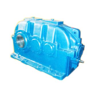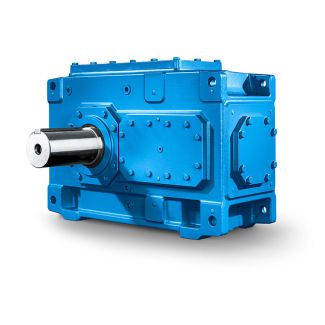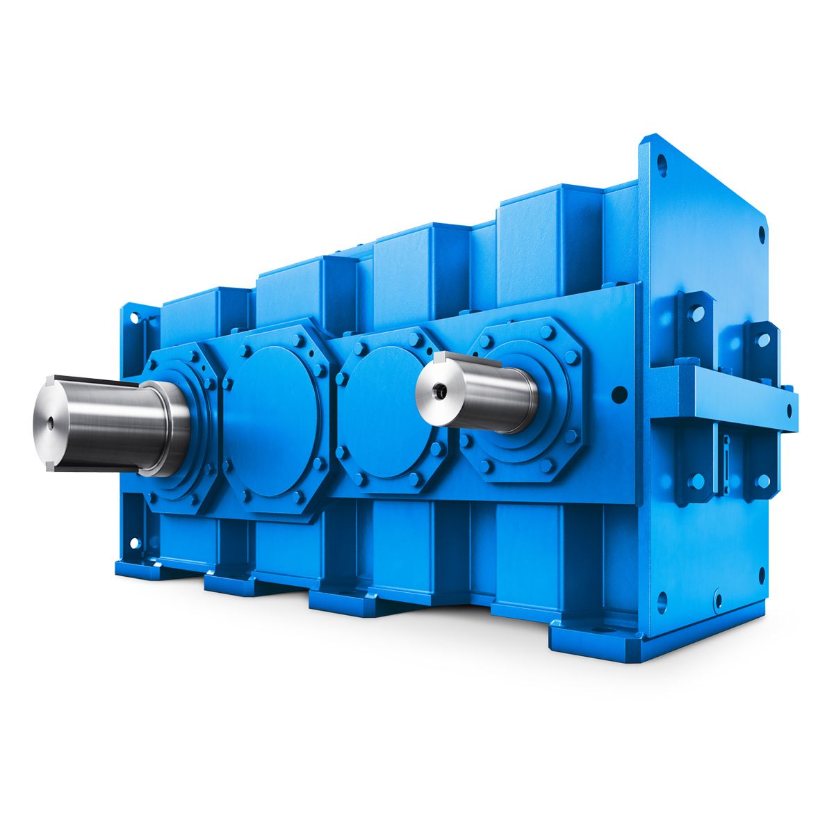

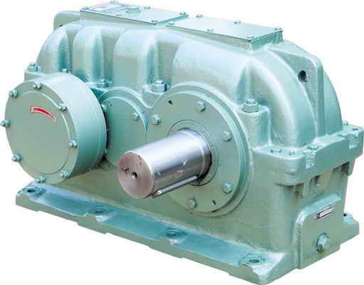
H2-VV-27-D www flender com Helical speed reduction gearbox H2
In stock
SKU
H2-VV-27-D
$471,428.57
Flender/Flender Gear Units/Helical speed reduction gearbox H2
2.2 Development Trends Production engineering has evolved in parallel with the gear cutting machines.Since the end of the 1s, dry cutting has steadily replaced the previouslydominant wet cutting which used cooling lubricants. An almost exclusive use is now made of
  cemented carbide tools, generally designed in the form of coated stick blades. Increased cutting speeds also reduce machining times substantially.
  Today machine concepts are specially adapted for the needs of dry cutting, where partic-ular attention must be given to the
  optimum removal of the hot metal chips. Moreand more direct drives with high rotation speeds are being used to achieve highcutting speeds even on smaller spiral bevel gears and hence using smaller tooldiameters. Work piece automatic loading into the gear cutting machines is steadilyexpanded. Efforts to integrate additional processes into the machines, such as deburring, are observed. 6.2.3 Tools 6.2.3.1 Technological Angles in the Cutting Edge Geometry The geometry of the bevel gear tooth ank is dened solely by the form and position of the cutting edge of the tool. Aside from the form, the technological angles of the cutting wedge are important for the manufacturing process. Figure 6.2 denes these angles. For the sake of simplicity, cutting wedge is shown with aplane front face and plane relief surfaces, and without tool edge radii.2 6 Manufacturing Process The cutting wedge consists of three sections: the primary cutting edge (, the tip cutting edge ( and the secondary cutting edge (. The front face is the plane which is made by these three sections of the cutting wedge. It is inclined by the side rake angle ( in relation to the plane normal to the direction of primary motion (. The relief surface behind the primary cutting edge is set back against the direction of primary motion by the side relief angle (, and the relief surface behind the secondary cutting edge is similarly set back by the side relief angle (. The tip rel
| Model Type | Helical speed reduction gearbox H2 |
|---|---|
| Gear Type | Helical Gear |
| Weight (kg) | 22000.000000 |
| Ratio Range | 1 : 8…20 |
| Low Speed Output | Solid shaft with parallel key acc. to DIN 6885/1 with reinforced spigot |
| Nominal Torque | 1230000 Nm |
| Mounting Arrangements | Vertical mounting position |
| Manufacturer | FLENOER-GRAFFENSTA |
| Country of Manufacture | Malaysia |
| Data Sheet & Drawings | H2-VV-27-D www flender com Helical speed reduction gearbox H2 |
Related Products