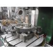
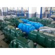
Flender/Flender Gear Units/Helical gear units H2
2 2 2 ... / ... 1 ... / ... 1 Fig. 4: Heating of gear unit without oilequalising tank of types .. and .. 1 Heating element 2 Temperature monitor For detailed illustration of the gear unit and the
  position of the addon parts, please refer to the drawings of the gearunit documentation. 5 / 1BA 5 en 0/2Never
  switch on the heating elements, unless complete immersion of the heating rod in the oil bath is ensured. Fire hazard!
  If heating elements are installed afterwards, the max. heating capacity (see Table on the outer surface of the heating element must not be exceeded. Table 2: Specific heating output Ho as function of the ambient temperature PHo (/cm)Ambient temperature 0.9 0.8.7+ 1 to 0 0 to 2 2 to 5 Operation and maintenance must be in accordance with the pertinent operating instructions. For technical data, refer to the list of equipment. 5.1 Oiltemperature monitoring Depending on the order specification, the gear unit may be fitted with Pt 1 resistance thermometer for monitoring the oil temperature in the sump. In order to measure the temperatures or temperature differences, the Pt 1 resistance thermometer should be connected to suitable instrument provided by the customer. The thermometer has connection head (protection type IP for the wiring. twoconductor circuit is provided by the manufacturer. However, the customer may fit his own three or fourconductor circuit if required. For control information, refer to the list of equipment. Observe the operating instructions relating to the device in all instances. 1 1 1 .. / .. 1 .. / .. 1 Fig. 4: Oiltemperature measurement on gear unit of types .. and .. 1 Pt 1 resistance thermometer For detailed illustration of the gear unit and the position of the addon parts, please refer to the drawings of the gearunit documentation. When operating and servicing the components, observe the operating instructions relating to the components. For technical data, refer to the data sheet and/or the list of equipme
| Model Type | Helical gear units H2 |
|---|---|
| Gear Type | Helical Gear |
| Weight (kg) | 2570.000000 |
| Ratio Range | 1 : 8…25 |
| Low Speed Output | Solid shaft with parallel key acc. to DIN 6885/1 with reinforced spigot |
| Nominal Torque | 107000 Nm |
| Mounting Arrangements | Vertical mounting position |
| Manufacturer | Flender GmbH |
| Country of Manufacture | Germany |
| Data Sheet & Drawings | H2-VV-14B gear box flender Helical gear units H2 |


