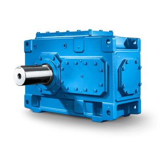
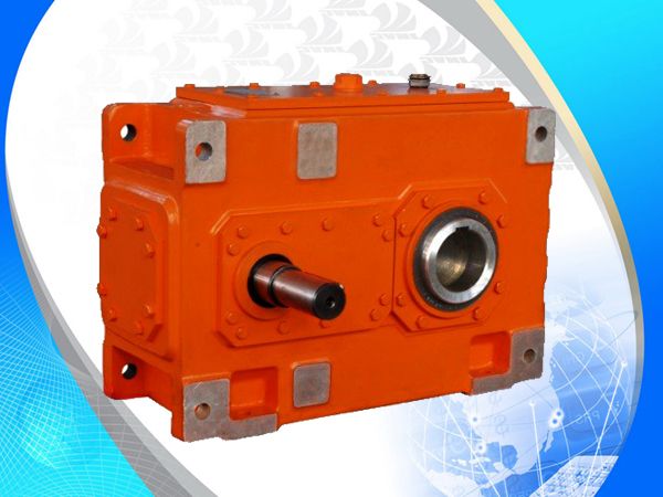
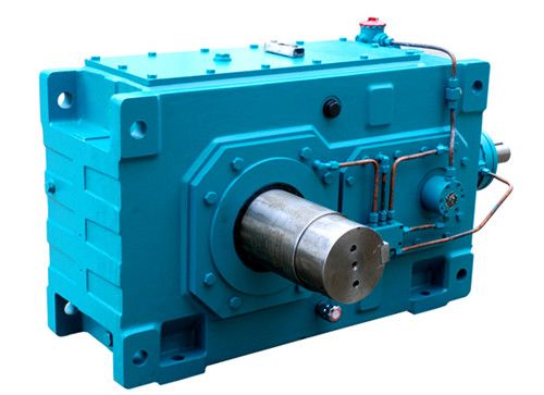

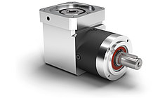
H2-VH-27-D flender windkraft Helical gear Reduction Boxes H2
In stock
SKU
H2-VH-27-D
$471,428.57
Flender/Flender Gear Units/Helical gear Reduction Boxes H2
1(Fig. 4.: Specific contact stiffness c0 1 CM/C1ctheo1 b4:3 with CM/C2.8 Fig. 4.4 Tooth stiffness and transmission error curves4.4 Stress Analysis 1 4.4.3.8 Load Capacity and Safety Factor Judging the load carrying capacity of the gears in gear system is
  analogous to what is done in the standardized calculation methods (see Sect. 4., namely one com- pares the calculated stresses
  to an acceptable strength value and species safety factor (Formulae (4., (4. and (4.): Safety factor Sstrength strain4:3 safety factor
  is calculated by comparing the calculated stress to maximum value from which damage results such as permanent deformation, crack initiation, brittle fracture of the surface zone, forced fracture, material fatigue (tooth fracture, pitting,micro-pitting) and scufng. The complex stress analysis relies on local calculation method (unlike the standard methods based on analytical/empirical approaches), in which stresses aredetermined for discrete locations on the tooth ank and tooth root. At constantexternal load, the maximum value of the stress is usually decisive and is comparedto strength value. If load spectrum is applied, damage due to the different load stages, which affect the size and position of the contact pattern, can be determined for each applied load. The strength values and - curves from [ ISO6 ] were determined experi- mentally and are linked to the calculation methods by converting the maximumpermissible torque determined in the test. The tooth ank and tooth root zone areconsidered at the same time and special inuences are accounted for by means ofinuence factors. The strength value itself also contains non-quantiable inu-ences. These must be accounted for in the local analysis and, if necessary, allowed for in local strength value. To ensure the local character of both the stress and strength values, the location with the maximum load need not necessarily be thelocation with the minimum safety factor. This procedure is based o
| Model Type | Helical gear Reduction Boxes H2 |
|---|---|
| Gear Type | Helical Gear |
| Weight (kg) | 22000.000000 |
| Ratio Range | 1 : 8…20 |
| Low Speed Output | Solid shaft with parallel key acc. to DIN 6885/1 with reinforced spigot |
| Nominal Torque | 1230000 Nm |
| Mounting Arrangements | Horizontal mounting position |
| Manufacturer | PT Flenindo Aditransimisi |
| Country of Manufacture | Tuvalu |
| Data Sheet & Drawings | H2-VH-27-D flender windkraft Helical gear Reduction Boxes H2 |
Related Products