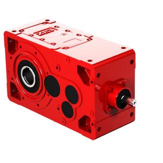
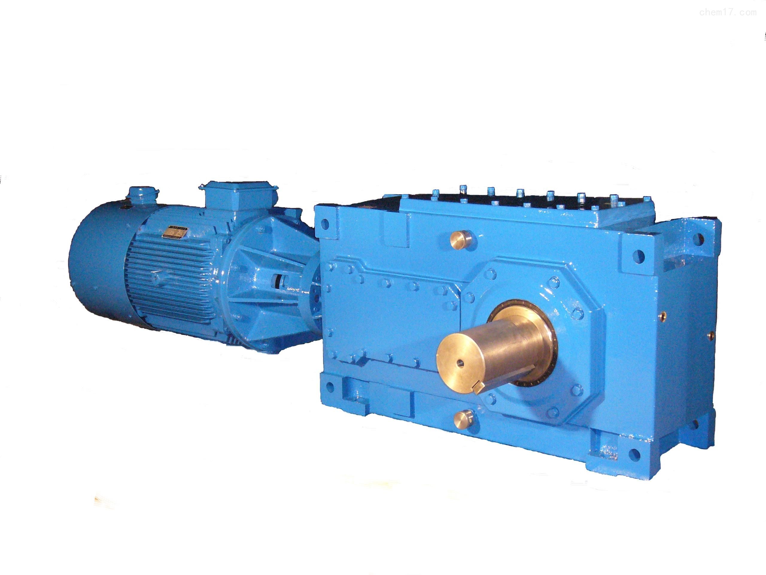
H2-VH-20-D siemens flender gearbox catalogue Helical gear Reduction Boxes H2
In stock
SKU
H2-VH-20-D
$160,714.29
Flender/Flender Gear Units/Helical gear Reduction Boxes H2
1.0/H1.7 kN/m2 Table 4 shows the foregoing values at different heights of the silo. The horizontal pressure is maximum at depth of 1.0 from top. Hoop tension /H1(2.8/H1.0/2.0) /H1.6 kN/. 4.2 Design of Component Parts 4.2.1 Design of Silo WallFor
  steel silo, the thickness of plate is determined from consideration of the compressive and tensile stresses to which the wall
  will be subjected by the total vertical weight. The vertical weight includes weight of the material stored above that level,
  self-weight of plate, Table 4 Computed Values of Pressures at Different Depths of Silo Height from top of silo 3.0 6.0 9.0 1.0 1.0 /z0e0.9 1.8 2.7 3.6 4.5 1/H1e/H1h/z0 0.5 0.8 0.9 0.9 0.9 ph(kN/m 1.7 2.5 2.2 2.7 2.8 pv(kN/m 1.7 2.5 2.2 2.7 2.8 2 Gupta and Bhattacharyya and lining material. The total weight over the cross-sectional area yields compressive stress. The Poisson effect of compressive stress along with the hoop stress yields totaltensile stress. For concrete silo, the horizontal ring reinforcements are provided to take care of the tensile stresses, whereas vertical bars are provided to take care of compressive or bending stresses. For silos with rectangular cross sections, if the wall spans vertically, horizontal reinforcement is provided to resist the direct tension, and vertical reinforcement to resistthe bending moments. The horizontal bending moments owing to the continuity at cornersshould be considered. 4.2.2 Design of the Hopper The total vertical load transferred at the hopper is calculated. The longitudinal stress and the hoop stresses are calculated for particular thickness of plate provided. If the stressesare within acceptable limits, the assumed thickness of the plate is adopted. The amount of horizontal reinforcement required for the hopper bottoms, provided in the form of an inverted truncated pyramid, is based on the horizontal direct tensioncombined with the bending moment. At the top of the slope, the bending moment and the component
| Model Type | Helical gear Reduction Boxes H2 |
|---|---|
| Gear Type | Helical Gear |
| Weight (kg) | 7500.000000 |
| Ratio Range | 1 : 7.1…22.8 |
| Low Speed Output | Solid shaft with parallel key acc. to DIN 6885/1 with reinforced spigot |
| Nominal Torque | 335000 Nm |
| Mounting Arrangements | Horizontal mounting position |
| Manufacturer | Flender Bocholt |
| Country of Manufacture | Russia |
| Data Sheet & Drawings | H2-VH-20-D siemens flender gearbox catalogue Helical gear Reduction Boxes H2 |
Related Products