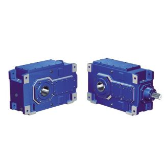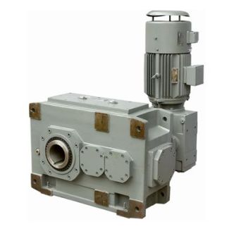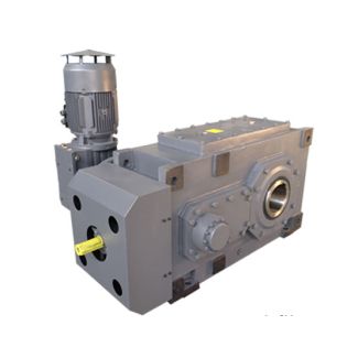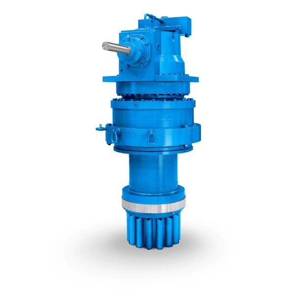

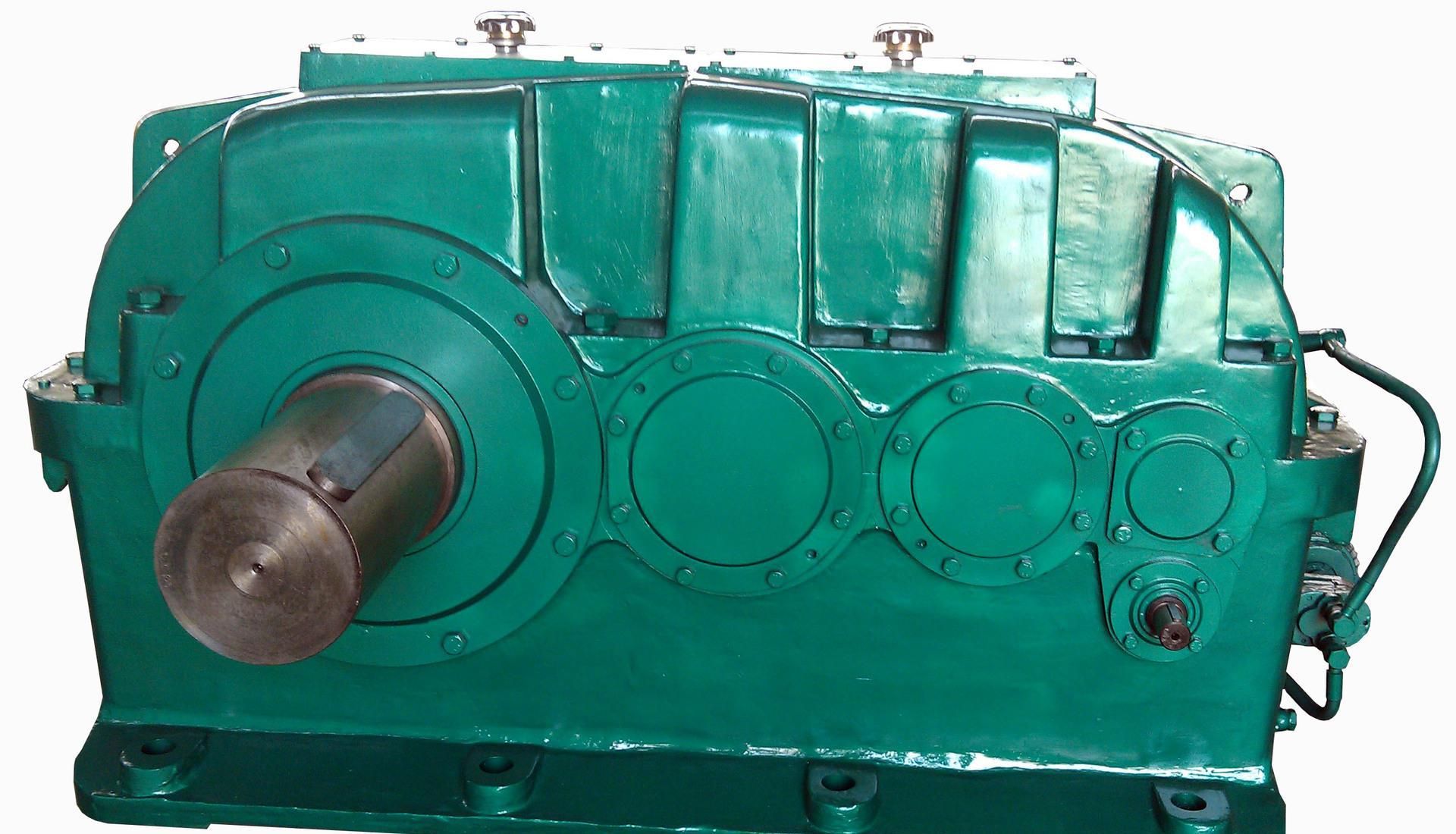
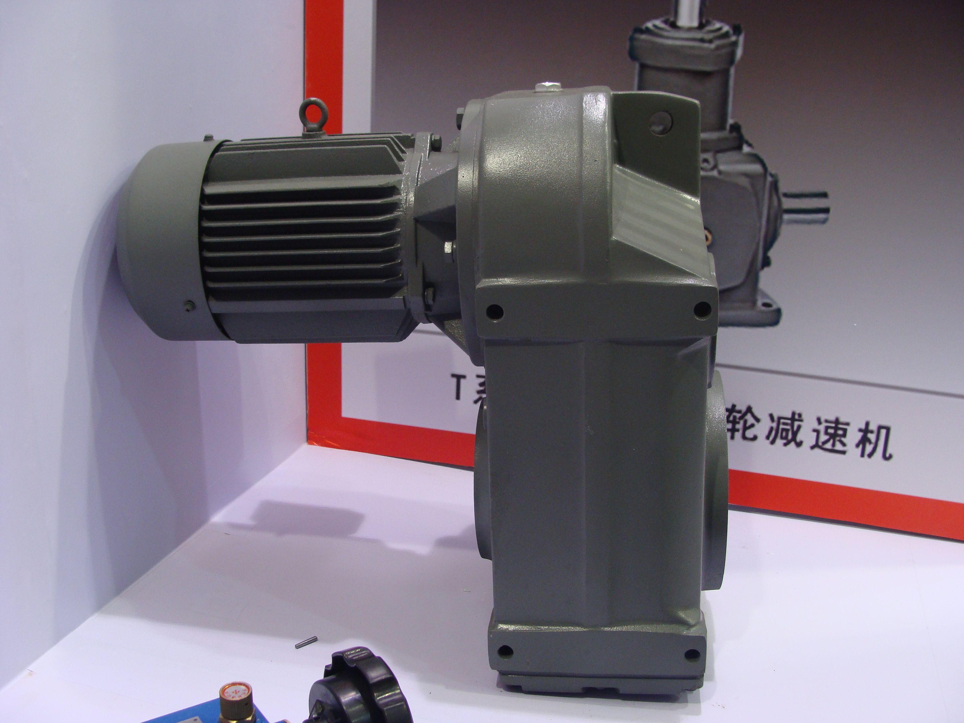

H2-SV-15-A siemens flender getriebe Helical speed reduction gearboxes H2
In stock
SKU
H2-SV-15-A
$73,285.71
Flender/Flender Gear Units/Helical speed reduction gearboxes H2
0.5s FnDand 0.5s FnCis considered as the tooth root cross-section Fn. All other variables are calculated with the effective normal pressure angle efor the drive or coast tooth ank, respectively. The calculations are iterative using the auxiliary variables , ,
  and . Iteration starts at/6 and is usually concluded with sufcient accuracy after few steps.Table 4.5 Calculating the tooth root
  stress Designation Formula No. Tooth root stressF1,2F0,2KAKvKFKF Fmtv bv/C1mmnYFa1,2YSa1,2YYBSYLS/C1KAKvKFKF(4. (4. FmtvFmt1,2cosv cosm1,2/C1T1,2 dm1,2cosv cosm1,2(4. YFa1,2factor considering the inuence of the
  tooth form YSa1,2stress correction factor considering stress increase due to the notch effect and the complex stress condition in the tooth root Ycontact ratio factor (tooth root) to convert the local stress deter- mined for load application at tip to the desired load position YBSbevel spiral angle factor considering shorter, inclined contact lines compared to the total face width YLSload sharing factor considering load sharing between two or more tooth pairs in contact KAapplication factor considering additional external loads resulting from operation Kvdynamic factor considering additional dynamic loads KFface load factor considering non-uniform load distribution along the face width KFtransverse load factor considering non-uniform load distribution between the meshing tooth pairs Table 4.6 Calculation of tooth form factors Fa1,2 for generated gears Designation Formula No. Tooth form factor YFa1,2hFaD, mmncosFanD , sFnD, mmn/C1/C1 cosnD,(4. where: FanD ,CanD,aD,(4. anD,CarccosdvbnD , dvanD ,/C1/C1(4. aD,C1 zvn 2xhmtaneD,Cxsm hi inveD,invan(4. (continued)4.2 Load Capacity Calculation 1 Stress correction factor Sa1,2 The stress correction factor Sa1,2accounts for the complex stress condition in the tooth root. It is calculated using the values for thetooth root chord Fn, the bending lever arm Faand the llet radius , and is determined according to
| Model Type | Helical speed reduction gearboxes H2 |
|---|---|
| Gear Type | Helical Gear |
| Weight (kg) | 3420.000000 |
| Ratio Range | 1 : 6.3…20 |
| Low Speed Output | Solid shaft with parallel key acc. to DIN 6885/1 |
| Nominal Torque | 143000 Nm |
| Mounting Arrangements | Vertical mounting position |
| Manufacturer | Flender Oy |
| Country of Manufacture | Vietnam |
| Data Sheet & Drawings | H2-SV-15-A siemens flender getriebe Helical speed reduction gearboxes H2 |
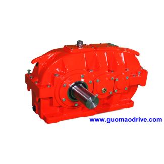
Related Products