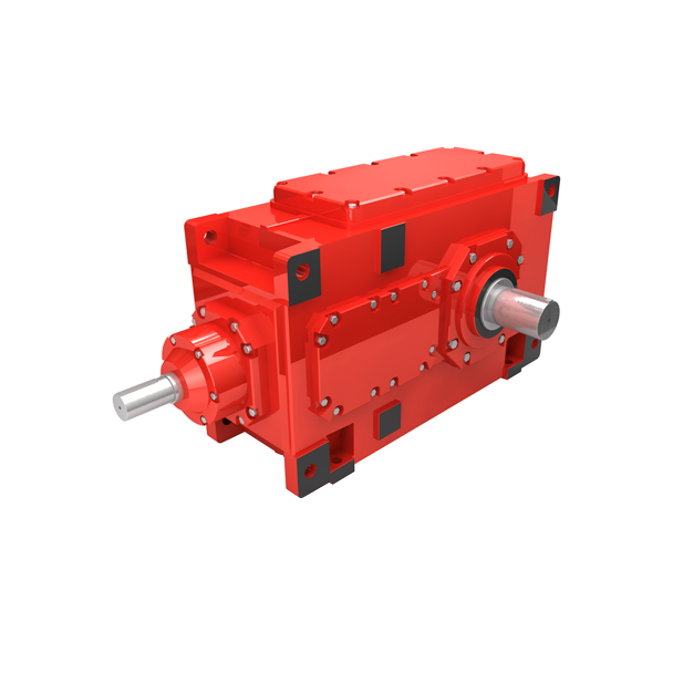
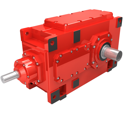
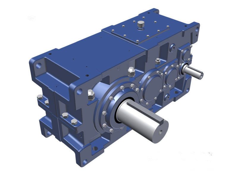
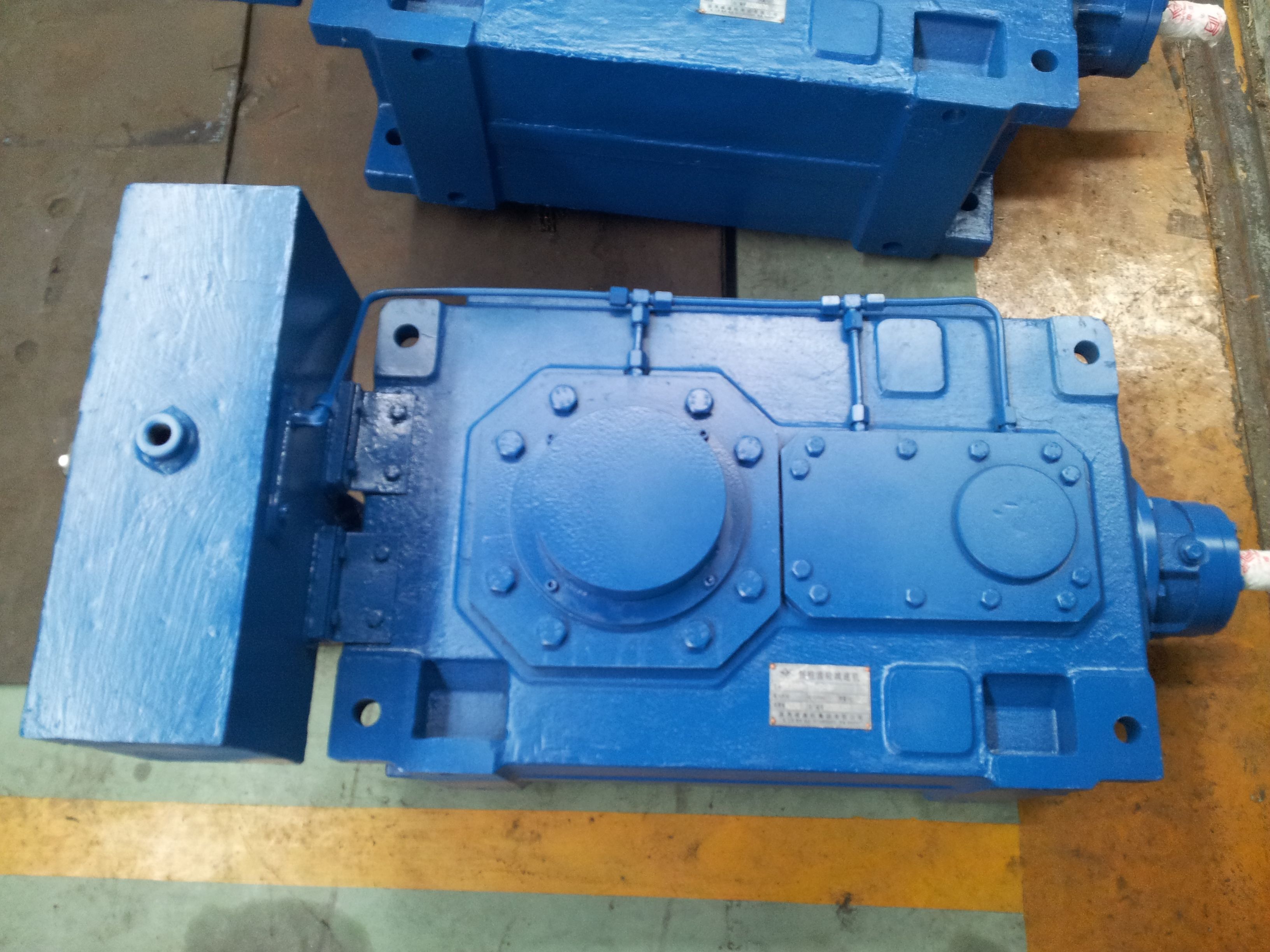
H2-SH-21-A flender flux laufroststütze 7b Helical gear box H2
In stock
SKU
H2-SH-21-A
$190,714.29
Flender/Flender Gear Units/Helical gear box H2
/C1ham1ham2 cos1(7. Tolerance diameter,wheeld T2dm2/C1, 5hmwham2 cos1dm2/C1ham2ham1 cos2(7.2 7 Quality Assurance deviation results if the measured value is larger than the desired value, and vice versa (see Fig. 7.. The differences, measured from tooth to tooth, are plotted on chart,
  starting with deviation 0 on tooth 1. Measurement data determine the single pitch deviation ptof the bevel gear, which is
  the maximum amount of all positive and negative single values in , and the cumulated pitch deviation , which is
  the difference between the maximum and minimum of the summed values (see Fig. 7.2 and also [ DIN3 ] [ ISO1 ]). The pitch tolerance may be determined for quality class designated using the formulae from Table 7.2. The factor between classes is 2p . The following rules, to round up or down, are employed: Fig. 7.1 Denition of pitch deviation. 1 theoretical tooth ank position 2 actual tooth ank 3 theoretical circular pitch 4 tolerance diameter Fig. 7.2 Determination of single and cumulative pitch deviations. tooth sequence number fptsingle pitch deviation Fxpitch deviation Fptotal cumulative pitch deviation7.1 Measurement and Correction 2 If the result is larger than 1 , it is rounded to the nearest whole number. If the result is larger than 5 , but smaller than 1 , it is rounded to the nearest 0.5 . If the result is smaller than 5 , it is rounded to the nearest 0.1 . 7.1.3 Flank Form Measurements 7.1.3.1 Fundamentals On cylindrical gears, the tooth prole is generally measured against desired reference involute, which is represented in the test chart as straight line. In thesame way, the actual tooth trace is compared to the desired tooth trace, likewise represented as straight line. On crowned cylindrical gears, deviations are toleranced by means of templates (-proles). Even when ignoring the fact thatcrowning can be in any direction, bevel gears do not have an involute tooth proleand, at least in the case of spiral bevel gears,
| Model Type | Helical gear box H2 |
|---|---|
| Gear Type | Helical Gear |
| Weight (kg) | 8900.000000 |
| Ratio Range | 1 : 7.1…20 |
| Low Speed Output | Solid shaft with parallel key acc. to DIN 6885/1 |
| Nominal Torque | 410000 Nm |
| Mounting Arrangements | Horizontal mounting position |
| Manufacturer | Flender (Australia) Pty. Ltd. |
| Country of Manufacture | Kyrgyzstan |
| Data Sheet & Drawings | H2-SH-21-A flender flux laufroststütze 7b Helical gear box H2 |
Related Products
