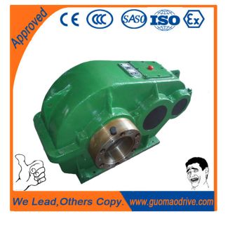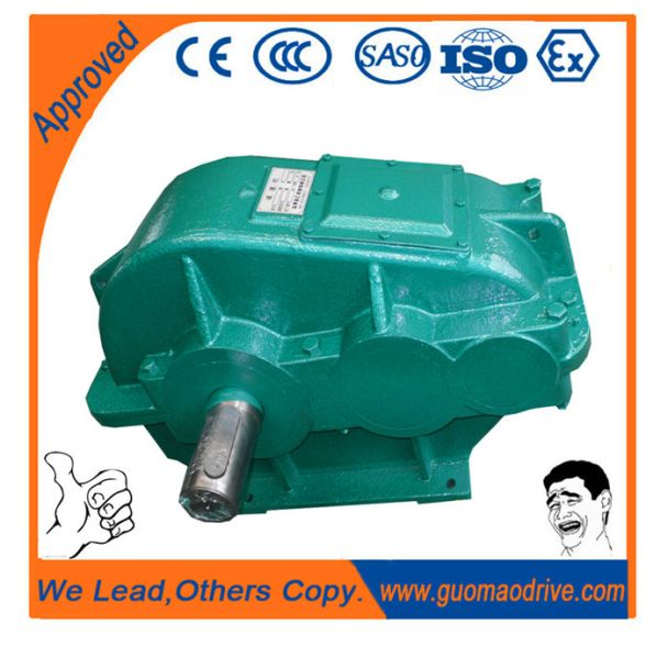
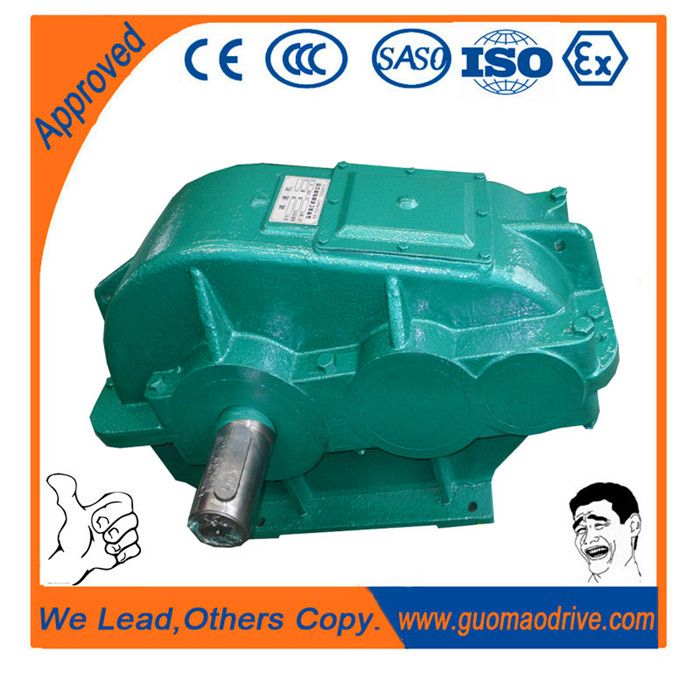
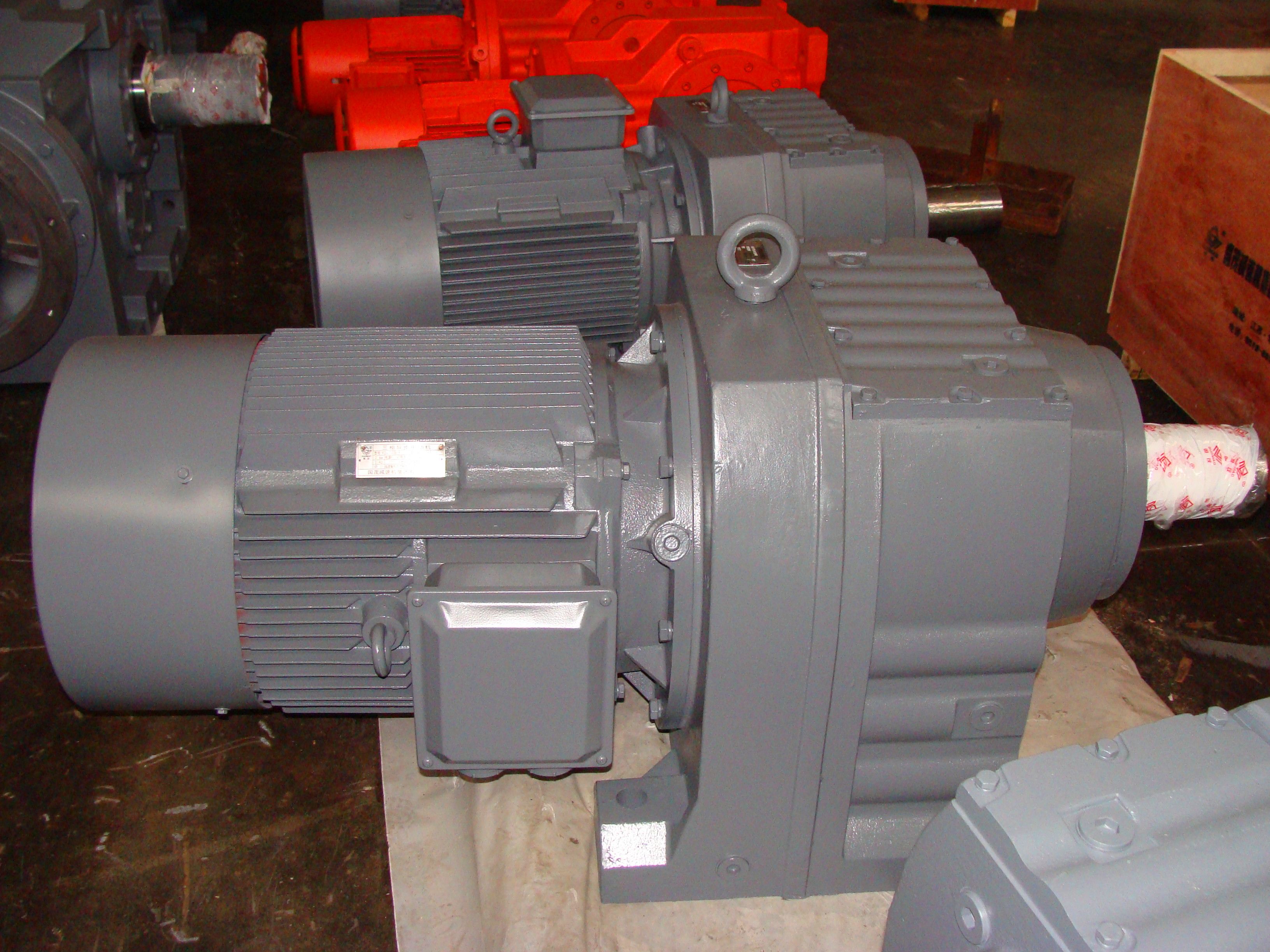


Helical gear Reduction Box H2 wilhelm flender H2-HH-27-A
In stock
SKU
H2-HH-27-A
$471,428.57
Flender/Flender Gear Units/Helical gear Reduction Box H2
7/1 ...7/1 Types B2, B3 and B4, upright mounting position, output at bottom ........................ 9/1 ...9/2 Types B2, B3 and B4, vertical mounting position ......... 8/1 ...8/1 Types H1, H2, H3 and H4, horizontal mounting position ..... 4/2 ...4/2 Types
  H1, H2, H3 and H4, vertical mounting position ......... 5/1 ...5/1 ATEX 9 Explosion protection overview .............. 1/2 Ordering information
  and ATEX codes .......................................... 1/2 ATH-SW2 (oil temperature monitoring) ....................... 1/7 Auxiliary drive ............................ 1/1 ...1/2 Load drive for type
  B3 ........... 1/1 , 1/2 ...1/2, 1/2 Maintenance drive for type B3 .......................1/1 ...1/1, 1/2 Speed monitoring for type B3 ......................................1/2 , 1/2 Backstop ........................................1/1 , 1/1 Bevel-helical gear units Horizontal mounting position ....... 7/1 ...7/1 Upright mounting position, output at bottom .......................... 9/1 ...9/2 Vertical mounting position ........... 8/1 ...8/1 Central holes, form DS in shaft ends DIN 3/1 .................................................... 1/2 Characteristic features .................................. 1/4 Climatic stress .......................................... 1/2 Coarse filter ................................................. 1/5 Coating system ......................................... 1/3 Color selection .......................................... 1/3 Connection dimensions ................. 1/1 ...1/8 Cooling Cooling coil ............................................. 1/6 Fan .......................................................... 1/6 Cooling coil ................................................. 1/6 Corrosivity category .................................. 1/2 Cover cap second shaft end ...................... 1/4 Cylindrical shaft ends ........................1/2 , 1/3 Design of the gear units ...................
| Model Type | Helical gear Reduction Box H2 |
|---|---|
| Gear Type | Helical Gear |
| Weight (kg) | 22000.000000 |
| Ratio Range | 1 : 8…20 |
| Low Speed Output | Hollow shaft with keyway acc. to DIN 6885/1 |
| Nominal Torque | 1230000 Nm |
| Mounting Arrangements | Horizontal mounting position |
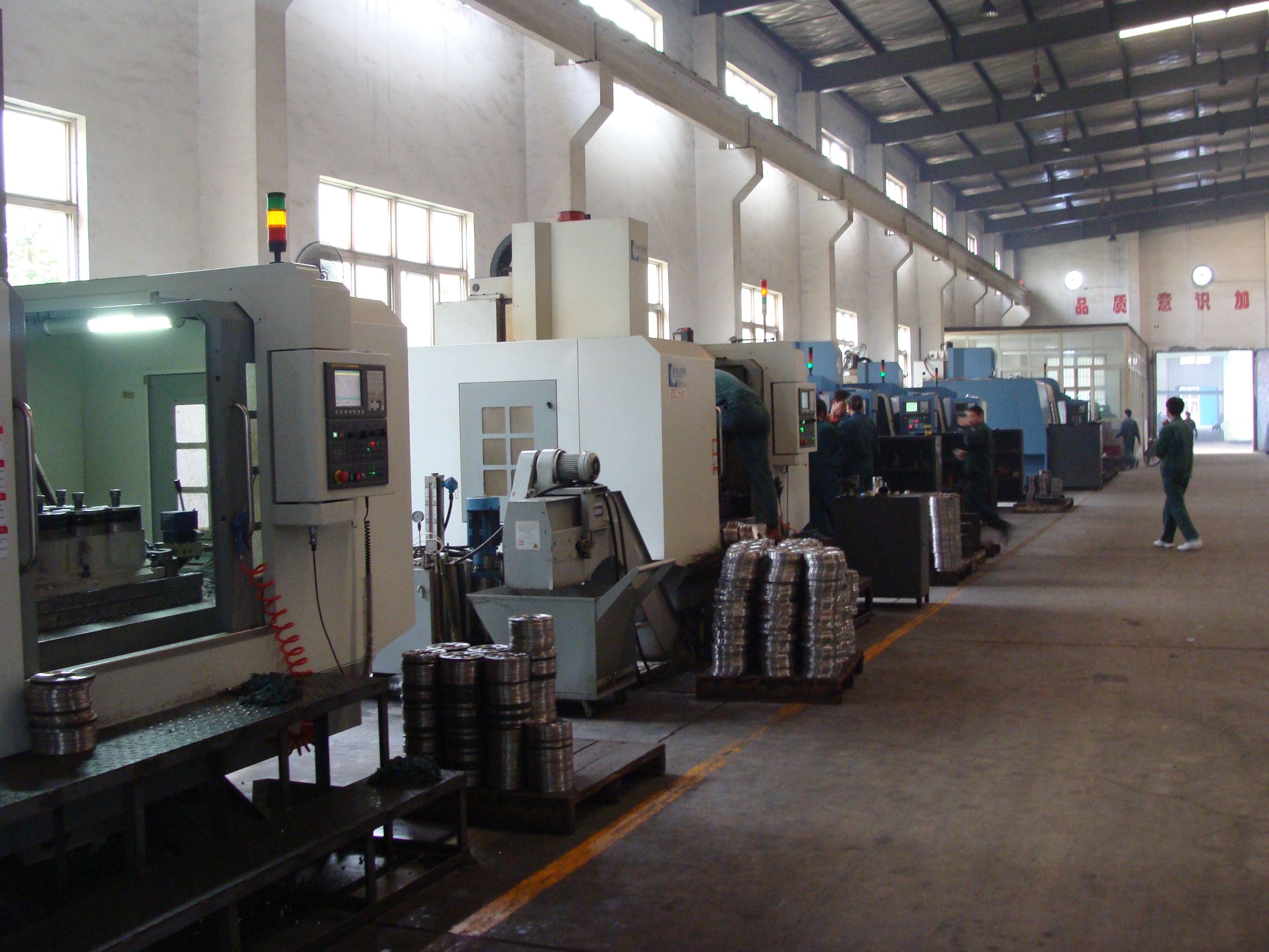
| Manufacturer | Flender Macneill Gears Ltd. |
| Country of Manufacture | Iraq |
| Data Sheet & Drawings | Helical gear Reduction Box H2 wilhelm flender H2-HH-27-A |
Related Products