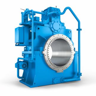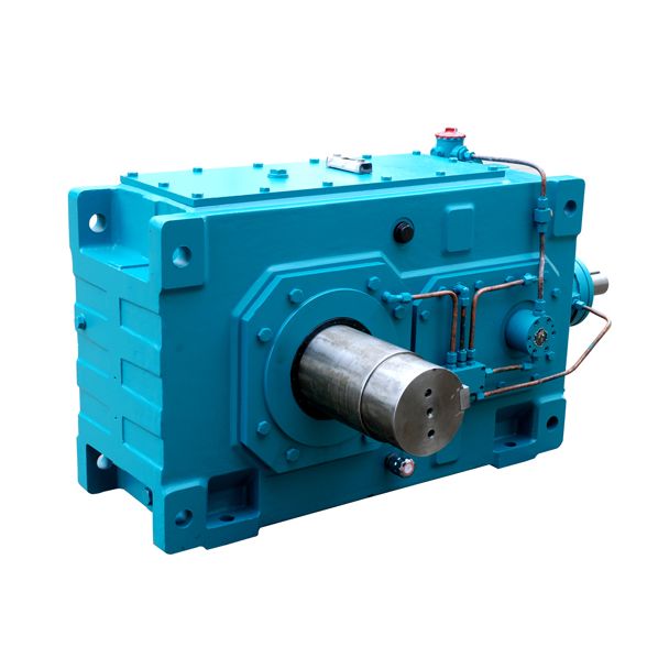
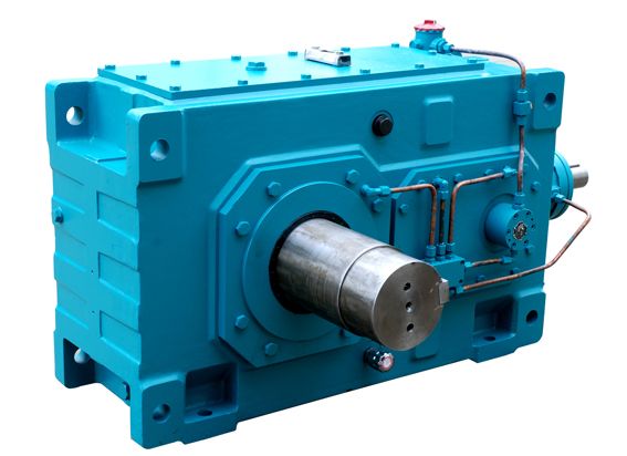
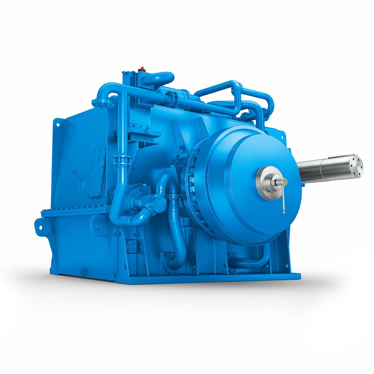
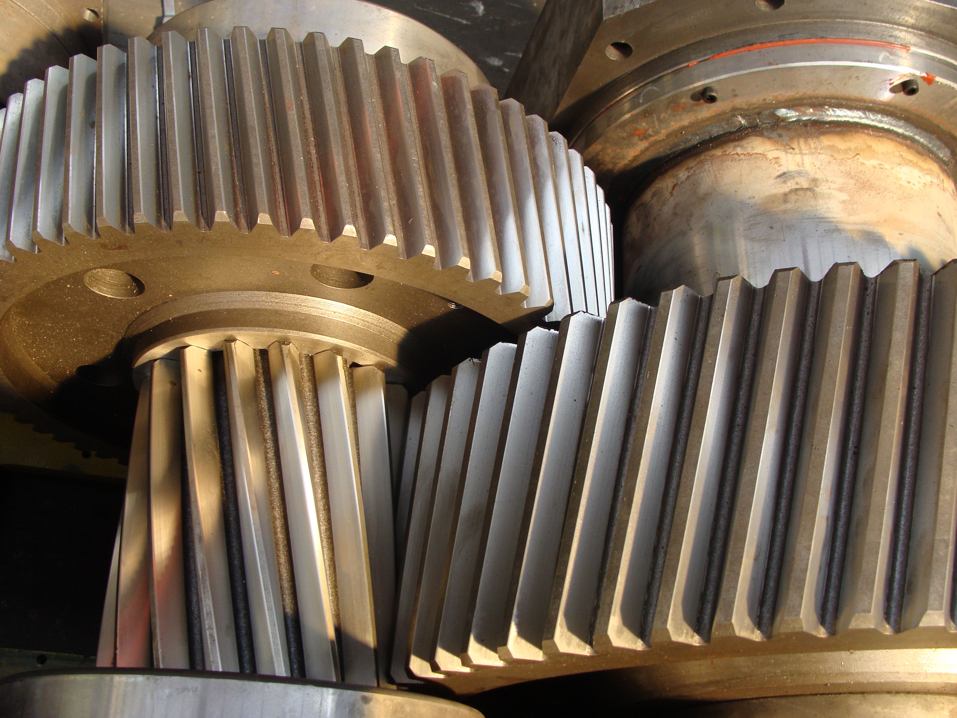
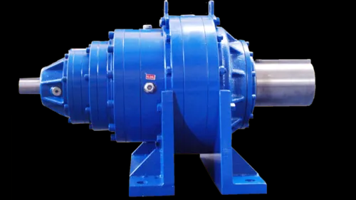
flender 173091 H2-DV-9-D Helical speed reducers H2
In stock
SKU
H2-DV-9-D
$17,785.71
Flender/Flender Gear Units/Helical speed reducers H2
AM1. Assembly is standard for Type and Assembly is standard for Type VR and will be furnished unless otherwise specified. All assemblies can be mounted in any position shown with Shaft horizontal by re-locating Oil Plugs in proper position. Mountings
  with Shaft vertical available at slight extra charge. Shafts can rotate in either direction, arrows show standard relative rotation. Opposite
  relative rotation available at no additional charge. To order with opposite relative rotation, insert letter between Assembly and Mounting code.
  Example: AOM1. Mountings shown below are available on an assembled to order basis. Filler, level and drain plugs are located on the back side of views shown. Special filler, level and drain plugs provided.FLOORM1MOUNTING POSIT ONS CEILINGM2 LASSEMBL TYPES VR1 M4M3W TOP VIEWV1 FVR1/VR2 Series FLENDER GRAFFENSTADEN bostongear speed reducers -1-BG 5/1MR1/R2, VR1/VR2 Series Selection ChartsR1/R2 Series & VR1/VR2 Series Spiral Bevel Gear Drives RatioInput RPMOutput RPMR/VR1 /VR1 /VR1 /VR1 Output Output Output Output HP Torque HP Torque HP Torque HP Torque 1:1 1 4 .2 1 8 .8 3 2 .1 9 5 .9 1 1 1 3 .1 1 5 .8 3 1 .5 1 4 .9 2 6 6 1 .9 1 3 .5 3 1 .4 1 2 .4 2 1 1 .4 2 .6 3 1 .8 1 4 .0 2 /VR2 /VR2 /VR2 /VR2Reducer2:1 8 2 .2 1 3 .7 2 1 .2 8 2 .6 1 1 5 1 .5 1 2 .5 2 8 .2 9 1 .2 1 6 3 .9 1 1 .5 2 5 .1 9 9 .4 1 1 5 .1 1 .2 2 .7 9 1 .5 1Increaser*1:2 3 2 .2 3 .5 3 .7 6 1 .2 2 1 2 1 .5 4 .2 2 .5 6 8 .2 2 1 .2 4 6 1 .9 4 .0 1 .5 7 5 .1 2 9 .4 4 1 2 .1 4 .2 .2 7 .7 2 1 .5 4 * NOTE: On 2:1 or 1:2 ratios, pinion will always be on shaft . Torque ( LB-INS ) / . . approx . 5% higher . Suggested Maximum Input Speeds** & VR1, & VR2 4 RPM & VR1, & VR2, & VR2 3 RPM & VR1, & VR1, & VR2 2 RPM ** Sound level, operating temperature and venting are usually affected at high operating speeds . ORDER BY CATALOG NUMBER OR ITEM CODE Horizontal Model R1/2 Vertical Model VR1/2 Series RatioItem Code Series RatioItem Code Assembly Type Assemb
| Model Type | Helical speed reducers H2 |
|---|---|
| Gear Type | Helical Gear |
| Weight (kg) | 830.000000 |
| Ratio Range | 1 : 6.3…22.4 |
| Low Speed Output | Hollow shaft with shrink disk |
| Nominal Torque | 33700 Nm |
| Mounting Arrangements | Vertical mounting position |
| Manufacturer | FLENOER-GRAFFENSTA |
| Country of Manufacture | Tunisia |
| Data Sheet & Drawings | flender 173091 H2-DV-9-D Helical speed reducers H2 |
Related Products