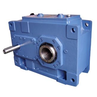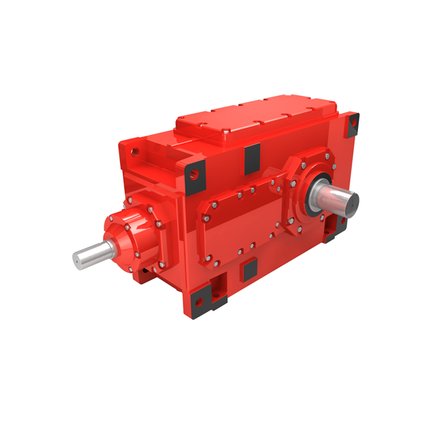
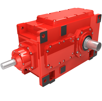
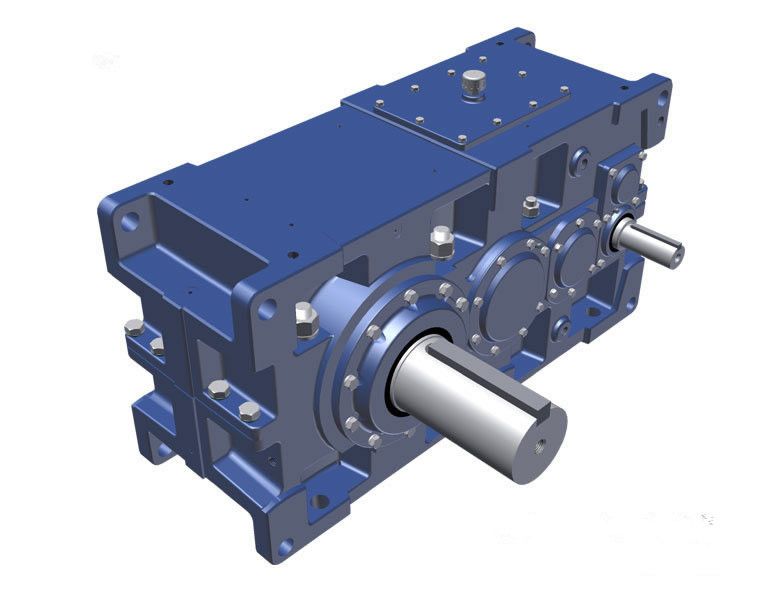


flender drives thandalam H2-DH-25-A Helical gear reducers H2
In stock
SKU
H2-DH-25-A
$334,285.71
Flender/Flender Gear Units/Helical gear reducers H2
al Journal of Engineering, Design and Technology, 2: 6(Onur Gven, Mehmet Ali Altunbaak plying the number of buckets by the bucket pitch. 4.5. Chain Link Section Calculation To select the chain material in the program, the mate - rial name
  is chosen from the dropdown menu on the main window. This action allows the program to obtain the materials breaking
  strength value and include it in the calculations. In the program, chain views and inner link sections for A1-B3-B4-B5-0-0-1 chains
  have been processed. Figure 6 displays only the A1 chain view and inner link section drawing detail. Minimum total cross-sectional areas at pea-pin con - nection of the chain types shown in the main window result form are determined from the AutoCAD project drawing for the pea cross-sectional areas of the select - ed chain types. These values are taken by the program according to the chain types from the generated table. If tensioning system weight project has been drawn, the project weight is entered. If there is no project drawing, an average weight should be entered into the program. 4.6. Drive Shaft Diameter Calculation Figure 7 illustrates the forces acting on the drive shaft. These forces cause shear, bending, and torsion in the shaft. T1 represents the weight of the material-filled side (), T2 represents the weight of the material-empty side (), and represents the shaft hub diameter (). Figure 7. Force distribution on the drive shaftThe bending moment Me (Nm) occurring in the shaft is calculated from equation (, where represents the length in meters (). The torsional moment Mb (Nm) occurring in the shaft is determined from equation (. ( ( The torsional moment Md (Nm) occurring in the shaft is calculated from the following equation. is the pow - er transmitted by the motor (kW), is the speed of the motor (revolutions per minute, rpm), and is the power transmission efficiency from the motor to the gearbox. For the sha
| Model Type | Helical gear reducers H2 |
|---|---|
| Gear Type | Helical Gear |
| Weight (kg) | 15600.000000 |
| Ratio Range | 1 : 6.3…20 |
| Low Speed Output | Hollow shaft with shrink disk |
| Nominal Torque | 860000 Nm |
| Mounting Arrangements | Horizontal mounting position |
| Manufacturer | Flender Guss Gmbh & Co. Kg |
| Country of Manufacture | New Zealand |
| Data Sheet & Drawings | flender drives thandalam H2-DH-25-A Helical gear reducers H2 |
Related Products