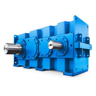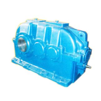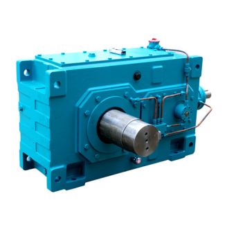
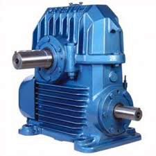

Helical speed reducer H2 gearbox flender catalogue H2-CV28A
In stock
SKU
H2-CV28A
$535,714.29
Flender/Flender Gear Units/Helical speed reducer H2
5, 5 5 5, 5 5 ... 5 5 ... 5 iN 5 1 4 3 iN 5.6 6 1 7 iN 6.3 6.3 6.7 1 8 iN 7.1 7.1 7.5 2 9 iN 8 8 8.5 2.4 1 iN
  9 . 5 2 5 1 1 2 iN 1 1 1.6 2 1 iN 1.2 1.2 1.8 3.5 1
  iN 1.5 1.5 1.2 3.5 1 iN 1 1 1 4 1 iN 1 1 1 4 2 iN 1
  8 9 0 2 4 iN 2 0 5 6 5 0 iN 6 3 2 8 0 iN 7 1 3 1 5 iN 8 0 3 5 5 Oil supply Dip lubrication Other oil supply Q0Y Auxiliary cooling Without auxiliary cooling 0 Auxiliary cooling with fan 1 Auxiliary cooling by cooling coil, connections to gear unit face 4 (end face 2 Auxiliary cooling by fan and cooling coil, connections to gear unit face 4 (end face 3 Auxiliary cooling by cooling coil, connections to gear unit face 1 (end face 4 Additional details see page 1/2. Siemens AG 2 Bevel-helical gear units ho rizontal mounting position Types B2, B3 and B4 Notes 7/2 Siemens MD 3.1 2 Siemens AG 2 Siemens MD 3.1 2 8/2 Type B2 Gear unit dimensions 8/2 Two-stage, gear unit sizes 5 to 5 8/4 Two-stage, gear unit sizes 5 and 5 8/6 Type B3Gear unit dimensions 8/6 Three-stage, gear unit sizes 5 and 5 8/8 Type B4Gear unit dimensions 8/8 Four-stage, gear unit sizes 5 to 5 8/1 Four-stage, gear unit sizes 5 to 5 8/1 Types B2, B3 and B4 8/1 Dimensions of oil expansion unit 8/1 Article No. overview Bevel-helical gear units vertical mounting position Siemens AG 2 Bevel-helical gear units vertical mounting position Type B2 Gear unit dimensions Two-stage, gear unit sizes 5 to 5 8/2 Siemens MD 3.1 2Selection and ordering data G_MD3_EN_0Fan Air inletA3 e3 b4 b3 n6 n3 ab2 b2 n4 n4 A2 A1 G3G1 hH l1 l3G6 h6 5 c1 f2 B1g bd1d6 ca. 3 Dimensions in mm Gear unit sizesInput Fan d1 l1 l3 d1 l1 l3 G1 G3 A1 A2 A3 B1 d6 G6 iN = 5 1 1 5 4 m6 9 7 3 m6 8 6 3 4 1 2 1 1 1 4 iN = 5 1 1 5 5 m6 1 9 4 m6 9 7 4 4 2 2 1 2 1 5 iN = 5 1 1 5 6 m6 1 9 5 m6 1 8 5 5 2 3 1 2 1 6 iN = 6.3 1 2 5 6 m6 1 9 5 m6 1 8 5 6 2 3 1 2 1 6 iN = 5 1 1 5 7 m6 1 1 6 m6 1 1 6 6 3 3 2 3 2 7 iN = 6 1 1 5 7 m6 1 1 6 m6 1 1 6 7 3 3 2 3 2 7 Gear unit sizes
| Model Type | Helical speed reducer H2 |
|---|---|
| Gear Type | Helical Gear |
| Weight (kg) | 25000.000000 |
| Ratio Range | 1 : 9…22.4 |
| Low Speed Output | Solid shaft without parallel key |
| Nominal Torque | 1400000 Nm |
| Mounting Arrangements | Vertical mounting position |
| Manufacturer | F. H. Transmissiones S.A |
| Country of Manufacture | Slovakia |
| Data Sheet & Drawings | Helical speed reducer H2 gearbox flender catalogue H2-CV28A |
Related Products