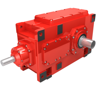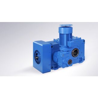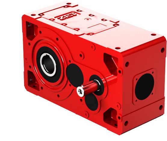
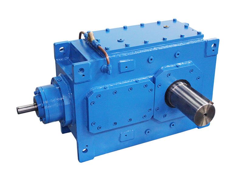
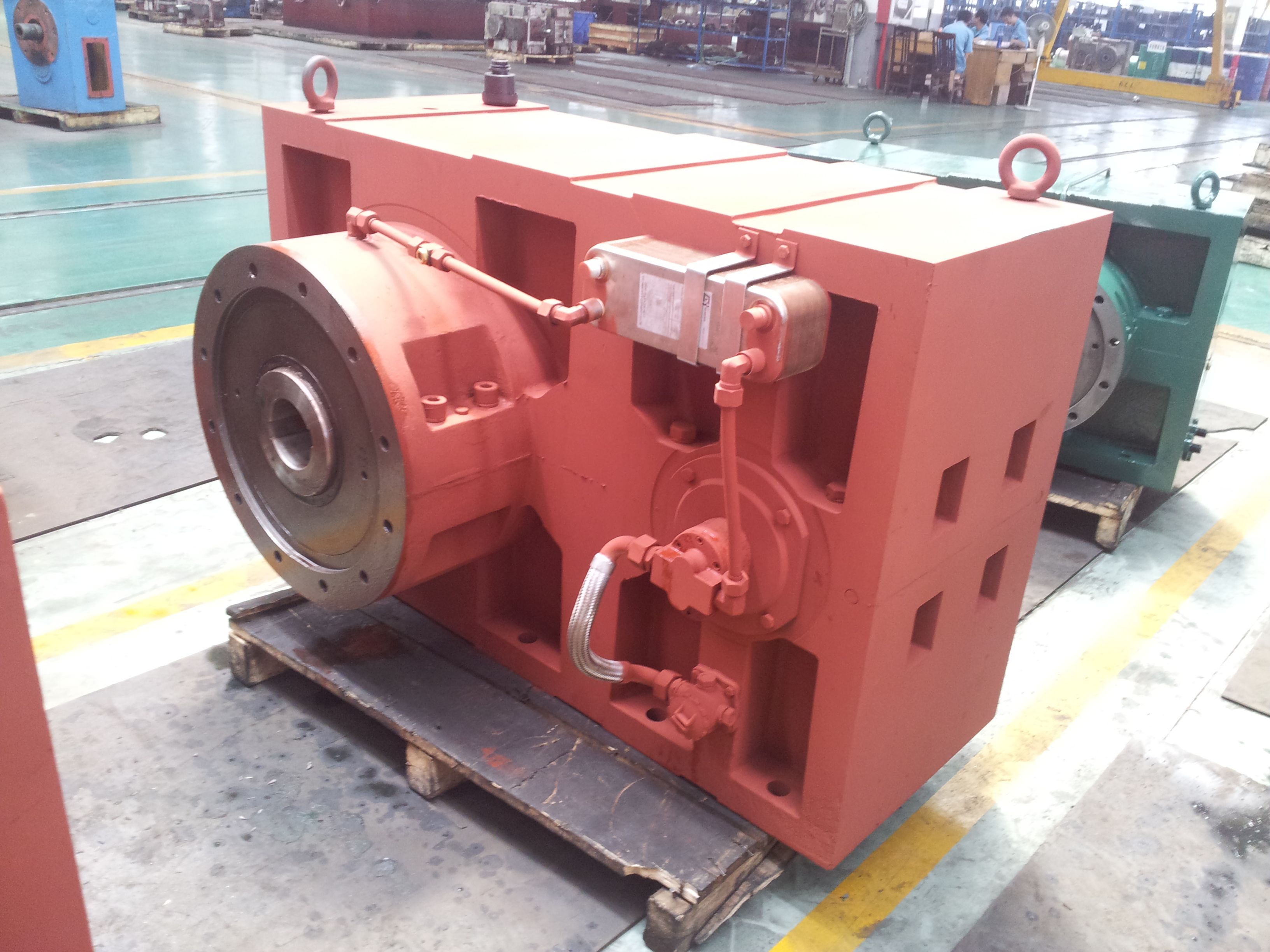
Flender/Flender Gear Units/Helical gear box H1
- M7 M5 - M6 M3 - M4 Dockside cranes (slewing, on gantry, ...) oating cranes and pontoon derriks Grab or magnet M7 - M8 M6 - M7 M4 - M5 Floating cranes and pontoon derricks for very heavy loads
  (usually greater than 1 ) M3 - M4 M3 - M4 Deck cranes Hook duty M4 M3 - M4 M2
  M3 Deck cranes Grab or magnet M5 - M6 M3 - M4 M4 - M5 M3 - M4 Tower cranes
  for building M4 M4 M3 M3 Derricks M2 - M3 M1 - M2 Railway cranes allowed to run in trains M3 - M4 M3 - M3 Automotive cranes Hook duty M3 - M4 M2 - M3 Here, 1 ...Pn is the operating cycle within the time cycle t1 ... tn.When using gear units with alternating loads as they usually exist in crane installations classi cation according to FEM is recommended. For this purpose, the factor for driven machine f1 and the peak torque factor f3 can be derived from table 2 on page 1 in accordance with the group of mechanism standard values M1...M8 in table 1 below - depending on the load (state of loading of mechanism L1...L and the duty (classes of utilization of mechanism T0...T. To take into account the load distribution in case of alternating loads within representative period of time , the cubic mean factor is calculated by: 0 1 5 1.0 0.4 0.1 t1 t2 t3T1 P1 T2 P2 T3 P3 0 1.7 3.3 1t1t2t3 5t4.0 0.7 0.4 0.2 0 5 1.0 0.4 t1 t2 0 9 1.0 0.8 t1 t2L1 L2 L3 L4 *) Only few typical cases of use are shown, by way of guidance, in this column. If the system is driven via an electric or hydraulic motor, factor for prime mover f2 = 1 may be provided. The factors shown on page 1 are empirical values. Prereq uisite for their application is that the machinery and equipment menti oned correspond to generally accepted design and load speci cations. In case of deviations from standard conditions, please refer to us. For driven machines which are not listed in this table, please refer to us. = + ... P1 Pt1 tPn Ptn t3 3 3Load Duration of use Service classi cation Siemens MD K2-1 2/2 Helical Gear Units With Extended Tot
| Model Type | Helical gear box H1 |
|---|---|
| Gear Type | Helical Gear |
| Weight (kg) | 2397.000000 |
| Ratio Range | 1 : 1.6…5.6 |
| Low Speed Output | Solid shaft with parallel key acc. to DIN 6885/1 |
| Nominal Torque | 75700 Nm |
| Mounting Arrangements | Vertical mounting position |
| Manufacturer | Flender Oy |
| Country of Manufacture | Grenada |
| Data Sheet & Drawings | Helical gear box H1 flender italia H1SV-13-C |
Related Products