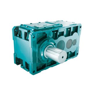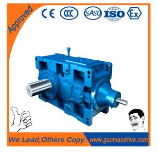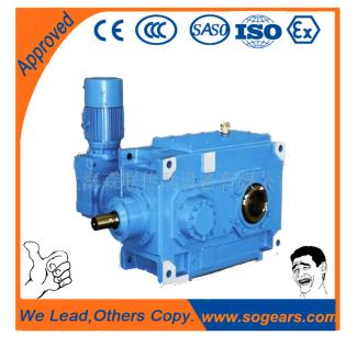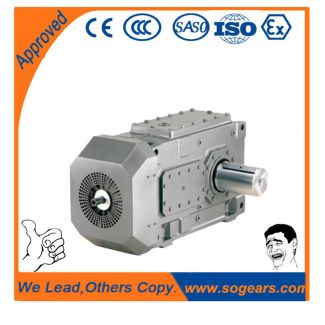
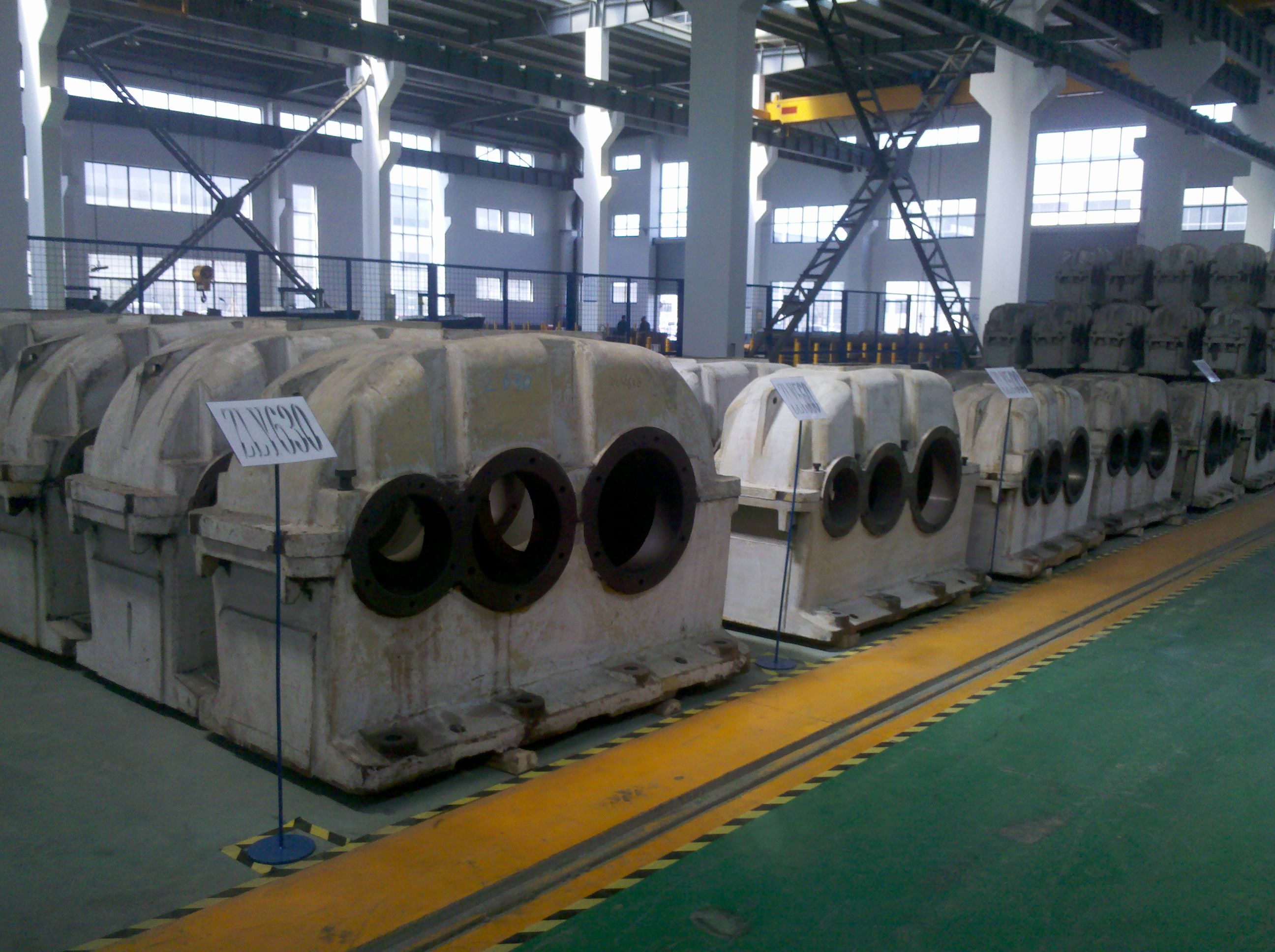
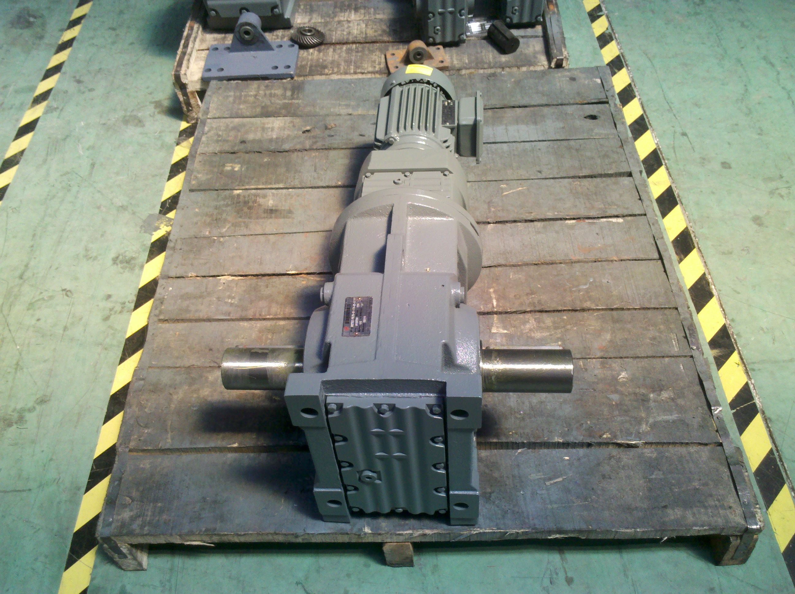
Bevel-helical speed reducer B4 ar unit sizes Overview Flender gear units of t B4VH-11-C
In stock
SKU
B4VH-11-C
$31,821.43
Flender/Flender Gear Units/Bevel-helical speed reducer B4
t applica tions. There are, however, certain precautions which should be exercised with what are thought to be self-locking characteristics of this reducer type. worm gear is generally said to be self-locking or irreversible when the gear cannot drive the
  worm when the lead angle of the worm is less than the friction angle and hence, reverse drive efficiency is
  zero. This static condition can be upset by vibrations from nearby machinery or other sources. Many worm gear reducers are
  not self-locking, and even particular size and ratio, which may appear to be, cannot be depended upon for this purpose. Also, reducer which holds the load when upward movement is stopped may not when the load inertia is moving downward and the motor is stopped. For complete locking assurance, it is recommended that fail-safe brake be used for such an application. Finding the required torque and drum RPM Torque (Lb. Ins.) = (Load) (Drum Radius) RPM = (Velocity) .2 (Drum Dia.) 8" WG.0Load Load -1-BG 5/1 FLENDER GRAFFENSTADEN bostongear speed reducersQApplication Considerations Example : An inclined belt conveyor is to carry cases of canned fruit. The belt is leather on wood conveyor bed. Ten cases will be on the conveyor at time, and each weighs 3 Lbs. The conveyor is inclined at 2 to the horizontal, and the head pulley diameter is 9. How much torque is required at the head pulley? Select .6 as the Application Factor (Table Determine weight: 1 3 = 3 Lbs. Determine belt pull: 3 .6 = 2 Lbs. Determine Torque: 2 9/2 = 2 4.5 = 9 Lb. Ins. Cylinders These applications deal principally with rotation of weight about horizontal centerline. Again, they are commonly subject to reducer overspecification. The table of Rolling Friction Factors in the section on turn tables may be used, since the supporting members will be essentially the same. For Roller Supported cylinders (Figure , the torque required will depend on the rolling friction fac tor and the angle between the
| Model Type | Bevel-helical speed reducer B4 |
|---|---|
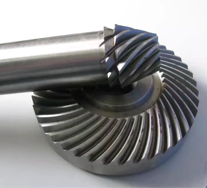
| Gear Type | Bevel Helical Gear |
| Weight (kg) | 1485.000000 |
| Ratio Range | 1 : 80…315 |
| Low Speed Output | Solid shaft with parallel key acc. to DIN 6885/1 with reinforced spigot |
| Nominal Torque | 61600 Nm |
| Mounting Arrangements | Horizontal mounting position |
| Manufacturer | FLENDER GUSS GMBH |
| Country of Manufacture | Peru |
| Data Sheet & Drawings | Bevel-helical speed reducer B4 ar unit sizes Overview Flender gear units of t B4VH-11-C |
Related Products