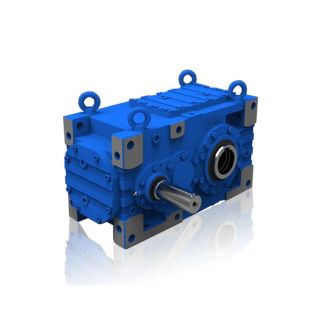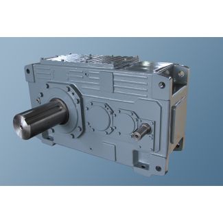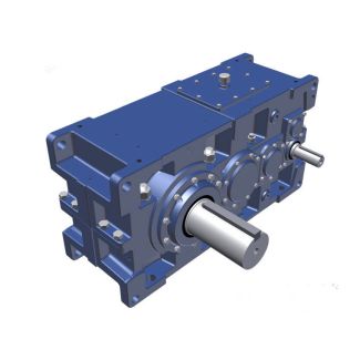

Bevel-helical gearbox B4 DIN Type D Hollow shaft for shrink disk FH Low s B4-HH-19-D
In stock
SKU
B4-HH-19-D
$145,714.29
Flender/Flender Gear Units/Bevel-helical gearbox B4
tional radial and/or axial forces (.. gear wheels, belt pulleys, disk flywheels, hydraulic couplings) are to be used, these must be agreed by contract. Couplings with peripheral velocities on the outer diameter of up to 3 / must be statically
  balanced. Couplings with peripheral velocities over 3 / mustbe dynamically balanced. For maintenance and operation of the couplings, refer to
  the specific operating instructions for the coupling. When installing the drives, make absolutely certain that the individual components are accurately
  aligned in relation to each other . Inadmissibly large errors in the alignment of the shaft ends to be connected due to angular and axial misalignments result in premature wear and material damage. Insufficiently rigid base frames or sub-structures can also during operationcause radial or axial misalignment, which cannnot be measured when the unit is at standstill. Note: For permissible alignment errors in the case of couplings supplied by FLENDER, please refer to the operating manuals for the couplings.If you use couplings by other manufacturers, ask which alignment errors arepermissible, stating the radial loads occurring. Note: The smaller the radial and angular misalignment between coupling parts on the shaft ends to be connected, the longer the service life and the higher the reliability of theequipment and the quieter the operation. Misalignments of the coupling parts in relation to each other can be caused by inaccurate alignment during assembly, but also by actual operation of the equipment (expansion due to heat, shaft deflection, insufficiently rigid machine frames, etc.).Caution! BA 5 EN 1.0Possible misalignments 5-1-2Kw KrKa Axial misalignment Ka)Angular misalignment Kw)Radial misalignment Kr) Alignment has to be done in two axial planes arranged perpendicular to each other. This can be done by means of ruler (radial misalignment) and feeler gauge (angular misalignment), as shown
| Model Type | Bevel-helical gearbox B4 |
|---|---|
| Gear Type | Bevel Helical Gear |
| Weight (kg) | 6800.000000 |
| Ratio Range | 1 : 80…315 |
| Low Speed Output | Hollow shaft with keyway acc. to DIN 6885/1 |
| Nominal Torque | 300000 Nm |
| Mounting Arrangements | Horizontal mounting position |
| Manufacturer | N.V. Flender Belge S.A. |
| Country of Manufacture | Germany |
| Data Sheet & Drawings | Bevel-helical gearbox B4 DIN Type D Hollow shaft for shrink disk FH Low s B4-HH-19-D |
Related Products