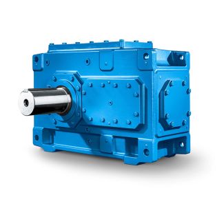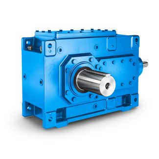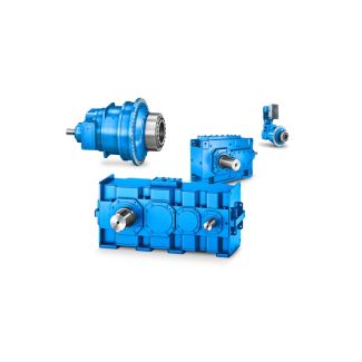

B4-FV-17-D valve In the basic design Flender FZG gear unit Bevel-helical gear units B4
In stock
SKU
B4-FV-17-D
$100,607.14
Flender/Flender Gear Units/Bevel-helical gear units B4
ydraulic motors, turbines1.0 Table 3 Peak torque factor 3 Load peaks per hour 1 - 5 6 - 3 3 - 1 > 1 f3 Uniform direction of load0.5 0.6 0.7 0.8 f3 Alternating direction of load0.7 0.9 1.1 1.2
  Design for power rating of driven machine 2 ) check for thermal capacity is absolutely essential Designed power corresponding to
  max. torque The listed factors are empirical values. Prere- quisite for their application is that the machin- ery and equipment
  mentioned correspond to generally accepted design and load specifica- tions. In case of deviations from standard conditions, please refer to us. For driven machines which are not listed in this table, please refer to us. Table 4 Thermal factor 4 Without auxiliary cooling or with fan cooling Ambient temperatureOperating cycle per hour (ED) 1 % 1 1.1 2 1.0 3 0.8 4 0.7 5 0.5 Table 5 Factor for altitude 6 Without auxiliary cooling or with fan cooling FactorAltitude (metres above MSL) up to 1 f6 1.0 Table 6 Oil supply factor 8 Horizontal gear units: 8 = 1.0 In case of forced lubrication: 8 = 1.0Tableau 1 Facteur des machines entranes 1 Machines de travailDure de fonctionne- ment journalier effective sous charge en heures 0,5> 0,5 -1> Transporteurs convoyeurs Convoyeurs godets 1,4 1,5 Treuils de puits 1,4 1,6 1,6 Machines dextraction 1,5 1,8 Convoyeurs bandes 1 kW1,0 1,2 1,3 Convoyeurs bandes 1 kW1,1 1,3 1,4 Transporteurs palettes 1,2 1,5 Tableau 2 Facteur des machines motrices 2 Moteurs lectriques, Moteurs hydrauliques, Turbines1,0 Tableau 3 Facteur de point max. 3 Pointes de charge par heure 1 - 5 - 3 3 - 1 > 1 f3 Direction perma- nente de la charge0,5 0,6 0,7 0,8 f3 Direction intermit- tente de la charge0,7 0,9 1,1 1,2 Explication pour la puissance absorbe ma- chine 2. ) Vrification thermique ncessaire Puissance calcule correspondant au couple ma
| Model Type | Bevel-helical gear units B4 |
|---|---|
| Gear Type | Bevel Helical Gear |
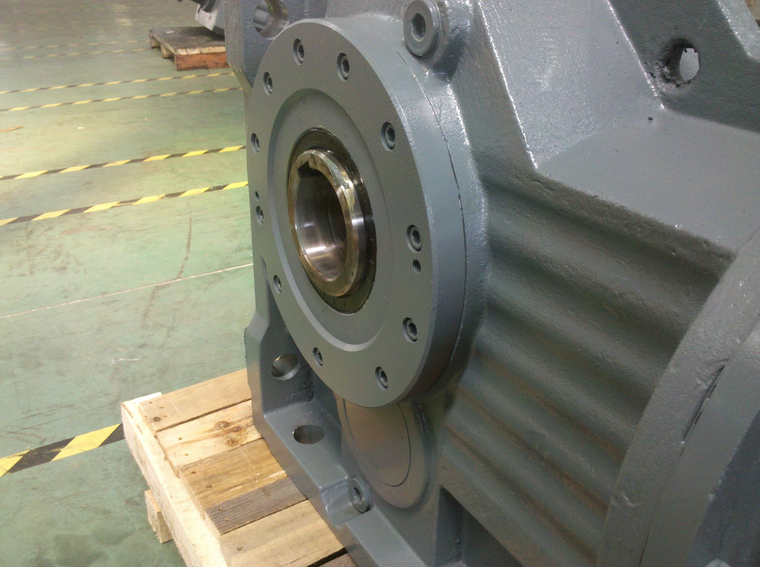
| Weight (kg) | 4695.000000 |
| Ratio Range | 1 : 80…315 |
| Low Speed Output | Flanged shaft |
| Nominal Torque | 200000 Nm |
| Mounting Arrangements | Vertical mounting position |
| Manufacturer | Flender LTD., KOREA |
| Country of Manufacture | Germany |
| Data Sheet & Drawings | B4-FV-17-D valve In the basic design Flender FZG gear unit Bevel-helical gear units B4 |
Related Products