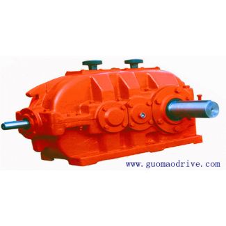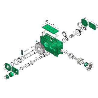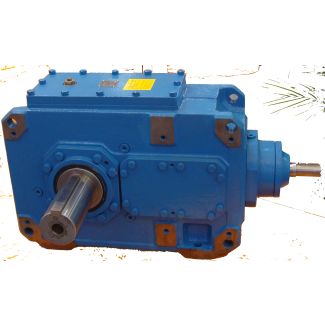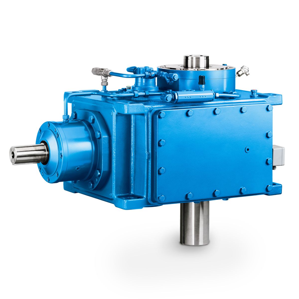
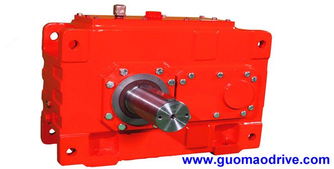
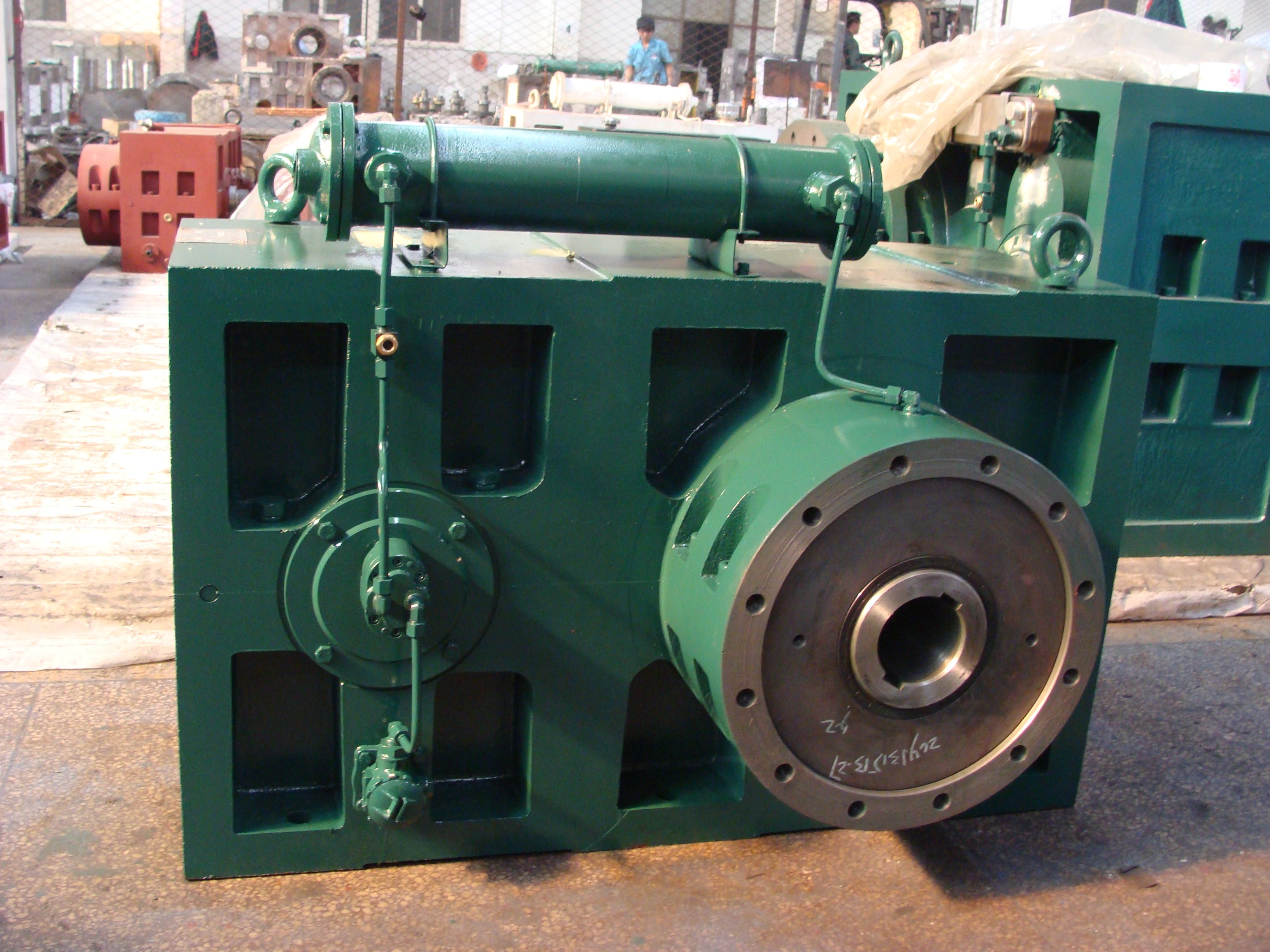
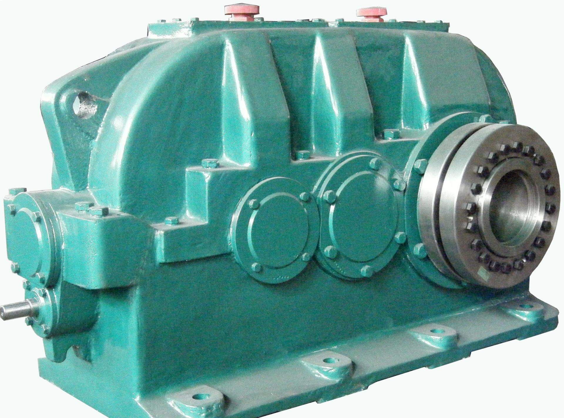
Bevel-helical gear unit B4 e and version A C BFH size to version B D B4-FH-26-A
In stock
SKU
B4-FH-26-A
$385,714.29
Flender/Flender Gear Units/Bevel-helical gear unit B4
Wrmegrenzleistungsfaktor fr Getriebe mit Lfterkhlung 1 ber-Aufstellungsort Ge- triebe-nber - setzung ikleine geschlossene Rume groe Rume, Hallen im Freien triebe- bauartn min-1g iGren Gren Grenbauart von ... bis 4 ... 6 ... 1 ... 1 ... 2 ... 2 ...
  6 ... 1 ... 1 ... 2 ... 2 ... 6 ... 1 ... 1 ... 2 ... 2 B2
  1,0 1,1 1,1 1,1 1,1 1,1 1,1 1,1 1,1 1,1 1,1 1,1 1,1 1,1 1,1 B2.. B3.. 1 5 ...
  9 1,4 1,4 1,4 1,4 1,3 1,4 1,4 1,4 1,4 1,3 1,4 1,5 1,4 1,4 1,3 T3..1 1,5 1,6 1,5 1,5 1,4 1,5 1,6 1,5 1,5 1,4 1,6 1,6 1,6 1,6 1,4 ) Windgeschwindigkeit 1 / ) Windgeschwindigkeit 2 / ) Windgeschwindigkeit 4 /sMD 2.6 2 2.0.2 1:1 Uhr Seite 1 1 Service Factors Table 1 Factor for driven machine 1 Driven machinesEffective daily operating period under load in hours Driven machines 0.5> 0.5 -1> Conveyors Bucket conveyors - 1.4 1.5 Hauling winches 1.4 1.6 1.6 Hoists - 1.5 1.8 Belt conveyors 1 kW1.0 1.2 1.3 Belt conveyors 1 kW1.1 1.3 1.4 Apron conveyors - 1.2 1.5Table 2 Factor for prime mover 2 Electric motors, hydraulic motors, turbines1.0 Table 3 Peak torque factor 3 Load peaks per hour 1 - 5 6 - 3 3 - 1 > 1 f3 Uniformdirection ofload 0.5 0.6 0.7 0.8 f3 Alternatingdirection ofload 0.7 0.9 1.1 1.2Design for power rating of driven machine 2 ) check for thermal capacity is absolutely essential Designed power corresponding to max. torqueThe listed factors are empirical values. Prerequi- site for their application is that the machinery andequipment mentioned correspond to generally accepted design- and load specifications. In case of deviations from standard conditions, pleaserefer to us. For driven machines which are not listed in this table, please refer to us. Table 4 Thermal factor 4 Without auxiliary cooling or with fan coolin
| Model Type | Bevel-helical gear unit B4 |
|---|---|
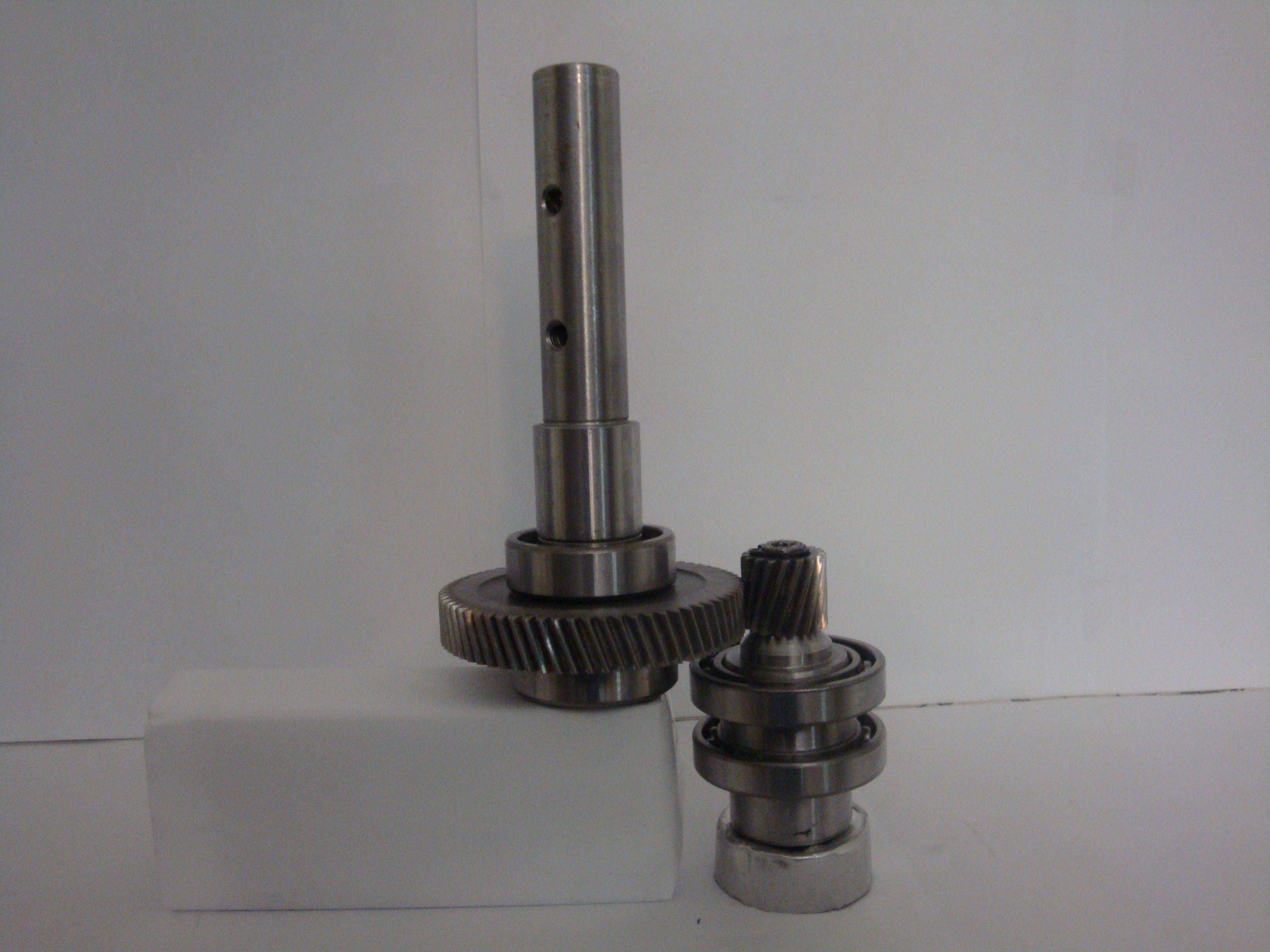
| Gear Type | Bevel Helical Gear |
| Weight (kg) | 18000.000000 |
| Ratio Range | 1 : 90…355 |
| Low Speed Output | Flanged shaft |
| Nominal Torque | 1030000 Nm |
| Mounting Arrangements | Horizontal mounting position |
| Manufacturer | Flender France S.A.R.L. |
| Country of Manufacture | Thailand |
| Data Sheet & Drawings | Bevel-helical gear unit B4 e and version A C BFH size to version B D B4-FH-26-A |
Related Products