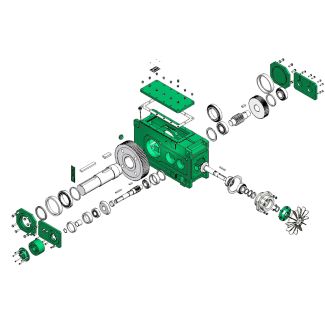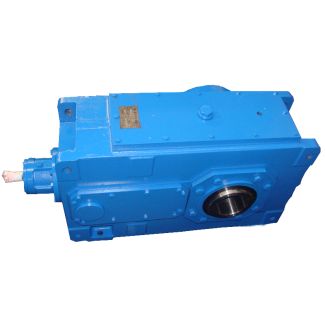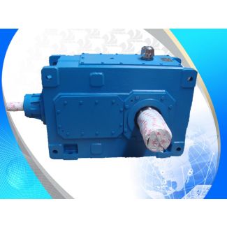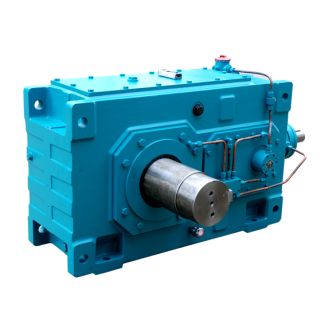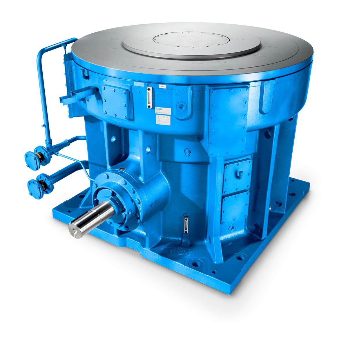
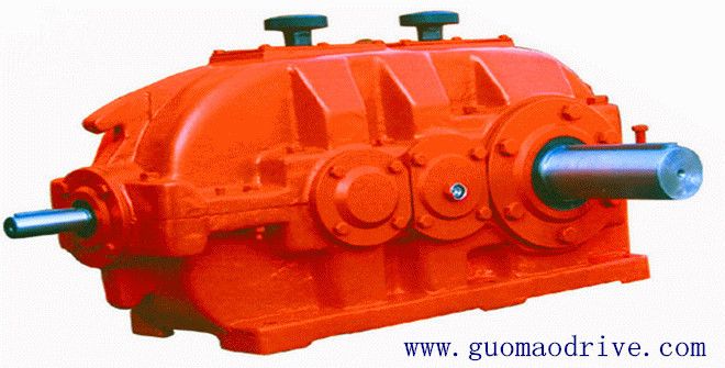
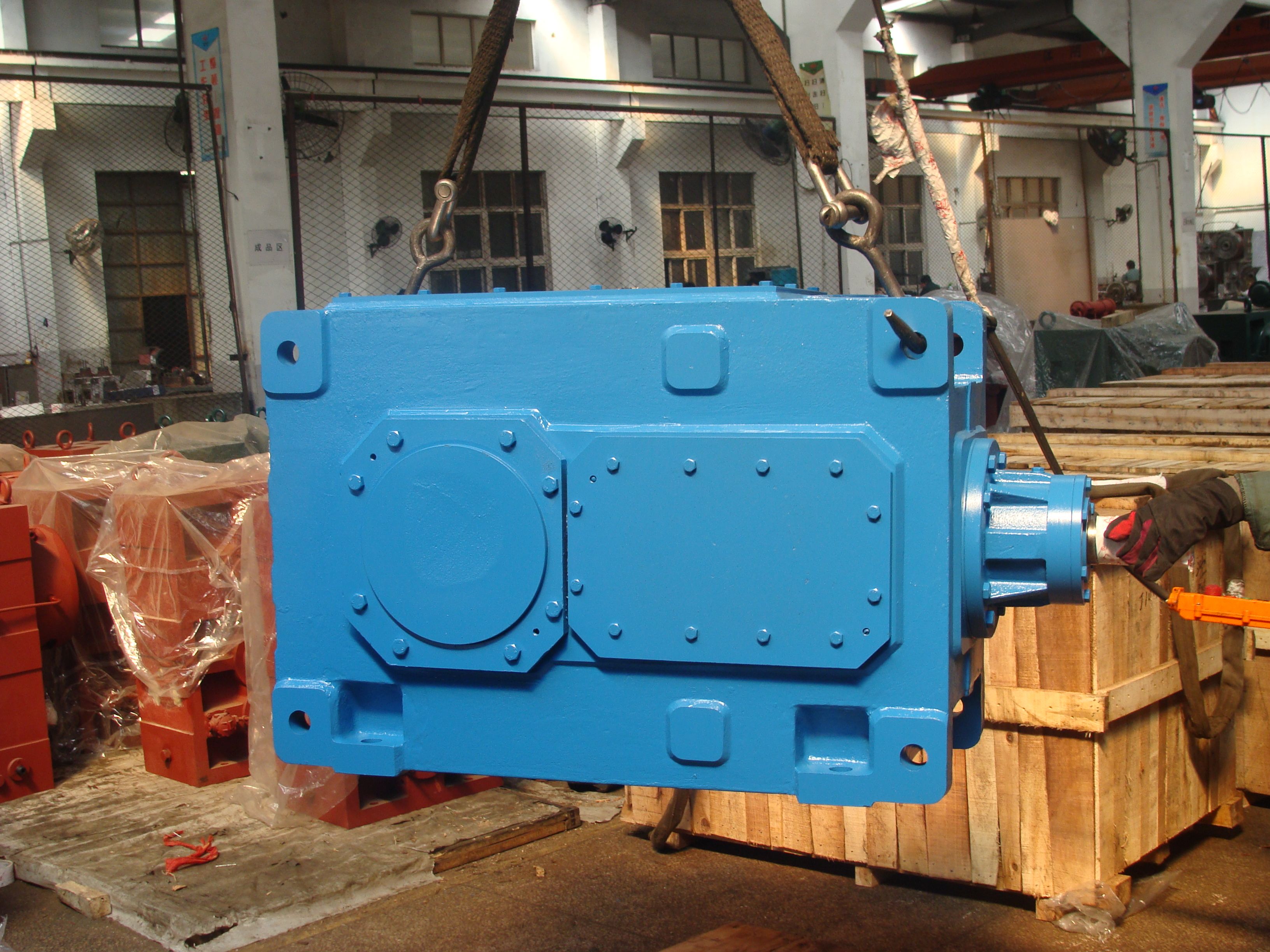

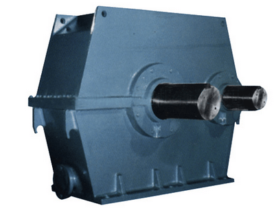
Bevel-helical gear Reduction Boxes B3 orizontal mounting position Type H Gear unit dimen B3-SH13-B
In stock
SKU
B3-SH13-B
$51,000.00
Flender/Flender Gear Units/Bevel-helical gear Reduction Boxes B3
o the lowest point in the piping system to be tested, to avoid overstressing of any of the lower portion of the system. For longer lines and vertical lines, two or more pressure gauges shall be installed at locations selected
  by the Engineer-in-charge. For lines containing check valves any of the following alternatives shall be adopted . Wherever possible pressurise
  up-stream side of valve. Replace the valve by temporary spool and re-install the val ve after testing. Provide blind on
  valve flanges and test the upstream and downstream of the line separately and remove the blind after testing. All these flanges, temporary gaskets shall be provided during testing and shall be replaced by permanent gaskets subsequently. For check valves in lines 1-1/2" and below, flapper or seat shall be 1 of 1 STANDARD TECHNICAL SPECIFICATION MECON LIMITED REGD. OFF: RANCHI 8 OIL & GAS SBU, DELHI DOCUMENT NO. Page 5 of 8 TITLE MEC//0/2/1 REVISION : 0 FLUSHING AND TESTING OF PIPING SYSTEMS EDITION : 1 removed during testing (if possible). After completion of test ing the flopper/ seat shall be refitted. Gas lines when hydrostatically tested shall be provided with additional temporary supports during testing as directed by Engineer-in-charge. Piping which is spring or counter weight supported shall be temporarily supported, where the weight of the fluid would overload the support. Retaining pins for spring supports shall be removed only after testing is completed and est fluid is completely drained. When testing any piping system, air or steam of approximately 2 kg/cm2 () may be used as preliminary test to detect missing gaskets etc. as this avoids the necessity of purging the gas to make repairs. However, this method may not be used for this purpose, if the steam temperature is more than the design temp. of the line. For jacketed pipes testing of core pipes shall be done on individual pieces where the pipe is con
| Model Type | Bevel-helical gear Reduction Boxes B3 |
|---|---|
| Gear Type | Bevel Helical Gear |
| Weight (kg) | 2380.000000 |
| Ratio Range | 1 : 12.5…71 |
| Low Speed Output | Solid shaft with parallel key acc. to DIN 6885/1 |
| Nominal Torque | 90700 Nm |
| Mounting Arrangements | Horizontal mounting position |
| Manufacturer | Flender..Ltd China(Tianjin) |
| Country of Manufacture | South Korea |
| Data Sheet & Drawings | Bevel-helical gear Reduction Boxes B3 orizontal mounting position Type H Gear unit dimen B3-SH13-B |
Related Products