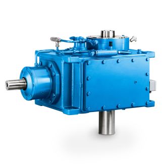
Bevel-helical gear boxes B3 nd Article No supplement for th to th position B3-CH-9-D
In stock
SKU
B3-CH-9-D
$19,285.71
Flender/Flender Gear Units/Bevel-helical gear boxes B3
oundation blocks: Hook the foundation blocks with washers and fastening bolts into the foundation fastening points on the gear unit housing (see figure . Note The fastening bolts must only be tightened when the concrete has set. 8 Fastening bolt
  2 Washer 3 Gear unit base 4 Set screw 5 Flat steel plate 6 Foundation 7 Final foundation height8 Prepared
  foundation height 9 Foundation block Fig. 1: Foundation block Using suitable lifting gear, place the gear unit on the concrete
  foundation. Align gear unit horizontally by in- and output shafts: when using stone bolts: with shims, when using foundation blocks, with the aid of the set screws (if available). If necessary with more powerful forces, use stops to prevent the unit from displacement. Before pouring the concrete foundation, fill up the openings in the foundation blocks with adequate material (. . polystyrene). Pour concrete into the recesses for the stone bolts or foundation blocks. When the concrete has set, tighten the hexagon nuts of the stone bolts or fastening bolts of the foundation blocks to the specified torque (see item 6.. NOTICE Property damage Damage to the gear unit from uneven tensioning of the hexagon nuts or fastening screws is possible. Tighten the hexagon nuts or fastening screws evenly. The gear unit must not be stressed excessively during the fastening process. 3 / 7BA 5 en 0/2.4 Couplings As rule, flexible couplings or safety slip clutches are used for driving the gear unit. If rigid couplings or other in- and/or output elements, which create additional radial and/or axial forces, (. . gear wheels, belt pulleys, disk flywheels, hydraulic couplings) are to be used, this must be agreed by contract. Note Couplings must be balanced in accordance with the specifications in the pertinent instructions manual. When operating and servicing the couplings, observe the operating instructions relating to the couplings. Increased system service life and reliability and reduced running noi
| Model Type | Bevel-helical gear boxes B3 |
|---|---|
| Gear Type | Bevel Helical Gear |
| Weight (kg) | 900.000000 |
| Ratio Range | 1 : 12.5…71 |
| Low Speed Output | Solid shaft without parallel key |
| Nominal Torque | 35700 Nm |
| Mounting Arrangements | Horizontal mounting position |
| Manufacturer | Flender de Mexico, S.A. de C.V. |
| Country of Manufacture | Ecuador |
| Data Sheet & Drawings | Bevel-helical gear boxes B3 nd Article No supplement for th to th position B3-CH-9-D |
Related Products