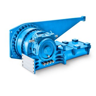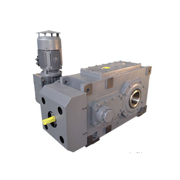
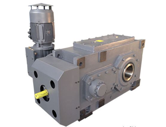
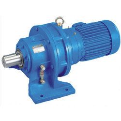
es PG kW type H n rpm o n r e q u e s tGear un B2VV-11-C Bevel-helical gear unit B2
In stock
SKU
B2VV-11-C
$49,178.57
Flender/Flender Gear Units/Bevel-helical gear unit B2
M1 2 2 1 2 2 4 5 1 1.5 1 5 5 5 1.6 M1 2 1 1 1.5 2 8 M1 3 2 1 2 3 4 5 1 1.5 1 6 5 5 2.5 M1 2 1
  1 1.5 2 8 M1 3 2 1 2 3 4 5 1 1.5 1 6 6 6 2.5 M1
  2 1 1 1.5 3 9 M1 3 2 1 3 3 5 5 1 1.5 1 6 6 6
  2.5 M1 2 1 1 1.5 3 1 M1 3 2 1 3 3 5 Note: Parallel key is not included in our scope of supply. Please order separately, if required.Assignment of central holes as specified on page 1/2. Material of driven machine shaft C6N or higher strength. Siemens AG 2 Connection dimensions Hollow shafts with spline in accordance with DIN 5 1/8 Siemens MD 3.1 2Dimensional drawings Types H2K., H3K., H4K., B3K., B4K. Types H2K., H3K., H4K., B3K., B4K. c2 -0.2.3 1.6 3.2r max End plate G_MD3_EN_0CirclipEnd plate Cover capOutputBush Driven machine shaft for thread center drilling Driven machine shaft for shrink disk connection, lubricated while mountingg2 G4 G4 c1d 9d8 d7 9D 2 1 II1 I2f1 d4 d3 d5 mind2 1D 3DH 2 Gear unit sizesDimensions in mm Driven machine shaft End plate Jacking thread Cir-clip Hollow shaft Cover cap Bolts for threaded central hole External spline d2 d3 d4d5f1l l1l2 rc1 c2 d7 d8 D9 Qty. DIN 4 D2D3G4DH 2g2 5 W8 3f 7.4 8h6 7 9 4 7 9 9 5M8 2 9 3 8 2 3M2 5 W9 3f 9.4 1h6 9 3 5 9 8 8 5M1 2 1 4 1 2 4M2 5 W9 3f 9.4 1h6 9 3 5 9 8 8 5M1 2 1 4 1 2 4M2 5 W1 3f1.4 1h6 1 1 3 6 3 8 9 6M1 2 1 4 1 1 1 3 5M2 5 W1 3f1.4 1h6 1 1 3 7 3 8 9 6M1 2 1 4 1 1 1 3 4M2 5 W1 3f1.4 1m6 1 1 3 8 4 1 3 8M1 2 1 4 1 1 2 3 4M3 5 W1 3f1.4 1m6 1 1 3 9 4 1 3 8M1 2 1 4 1 1 2 3 4M3 5 W1 5f1 1m6 1 1 5 1 1 4 1 3 9M1 2 1 4 1 1 2 3 4M3 5 W1 5f1 1m6 1 2 5 1 1 4 1 3 9M1 2 1 4 1 1 2 4 4M3 5 W1 5f1 1m6 1 2 5 1 1 5 1 3 M1 2 2 4 1 1 3 4 5M3 5 W1 5f1 2m6 1 2 5 1 1 5 1 3 M1 2 2 4 1 2 3 4 6M3 Assignment of central holes as specified on page 1/2. Material of driven machine shaft C6N or higher strength. Siemens AG 2 Siemens MD 3.1 2 1/2 Shaft seals 1/2 Radial shaft seal 1/2 Taconite 1/4 Labyrinth seal 1/5 Oil circulation lubrication 1/5 Flange-mounted pump, type H1, horizonta
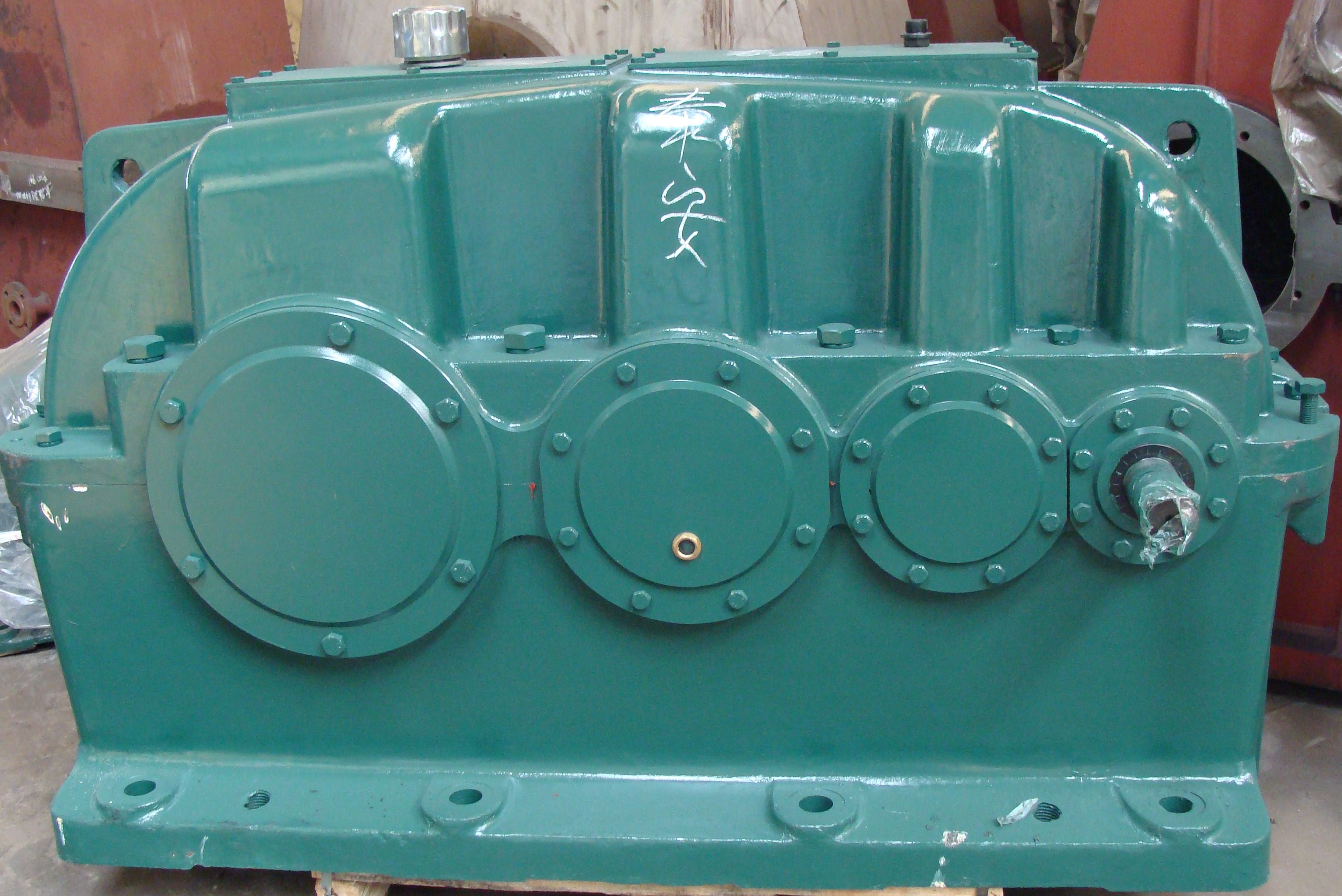
| Model Type | Bevel-helical gear unit B2 |
|---|---|
| Gear Type | Bevel Helical Gear |
| Weight (kg) | 2295.000000 |
| Ratio Range | 1 : 5…18 |
| Low Speed Output | Solid shaft with parallel key acc. to DIN 6885/1 with reinforced spigot |
| Nominal Torque | 54000 Nm |
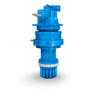
| Mounting Arrangements | Vertical mounting position |
| Manufacturer | FLENDER GUSS GMBH |
| Country of Manufacture | Germany |
| Data Sheet & Drawings | es PG kW type H n rpm o n r e q u e s tGear un B2VV-11-C Bevel-helical gear unit B2 |
Related Products