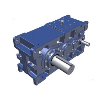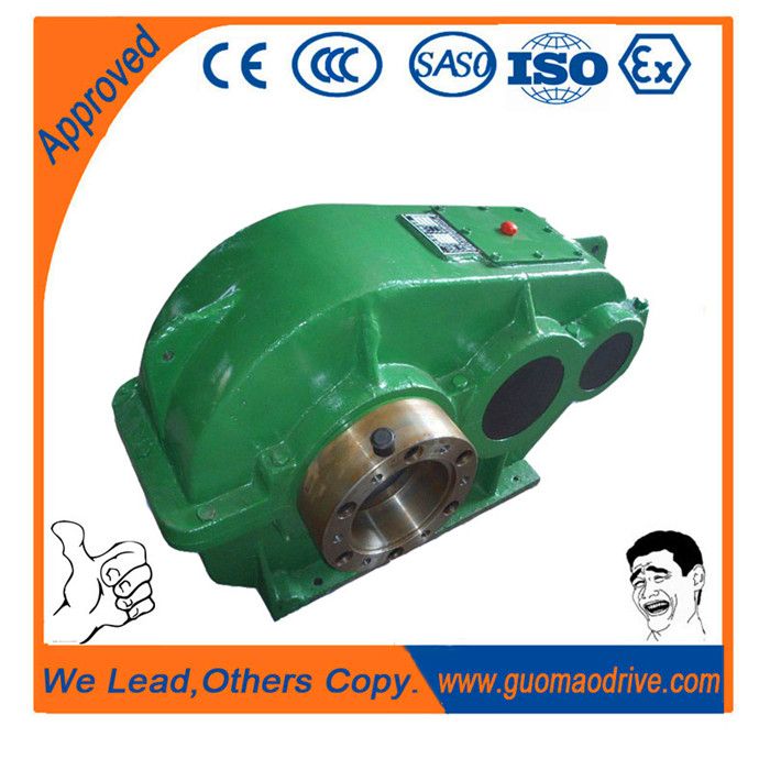
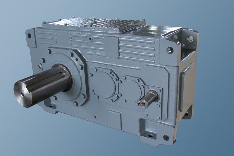

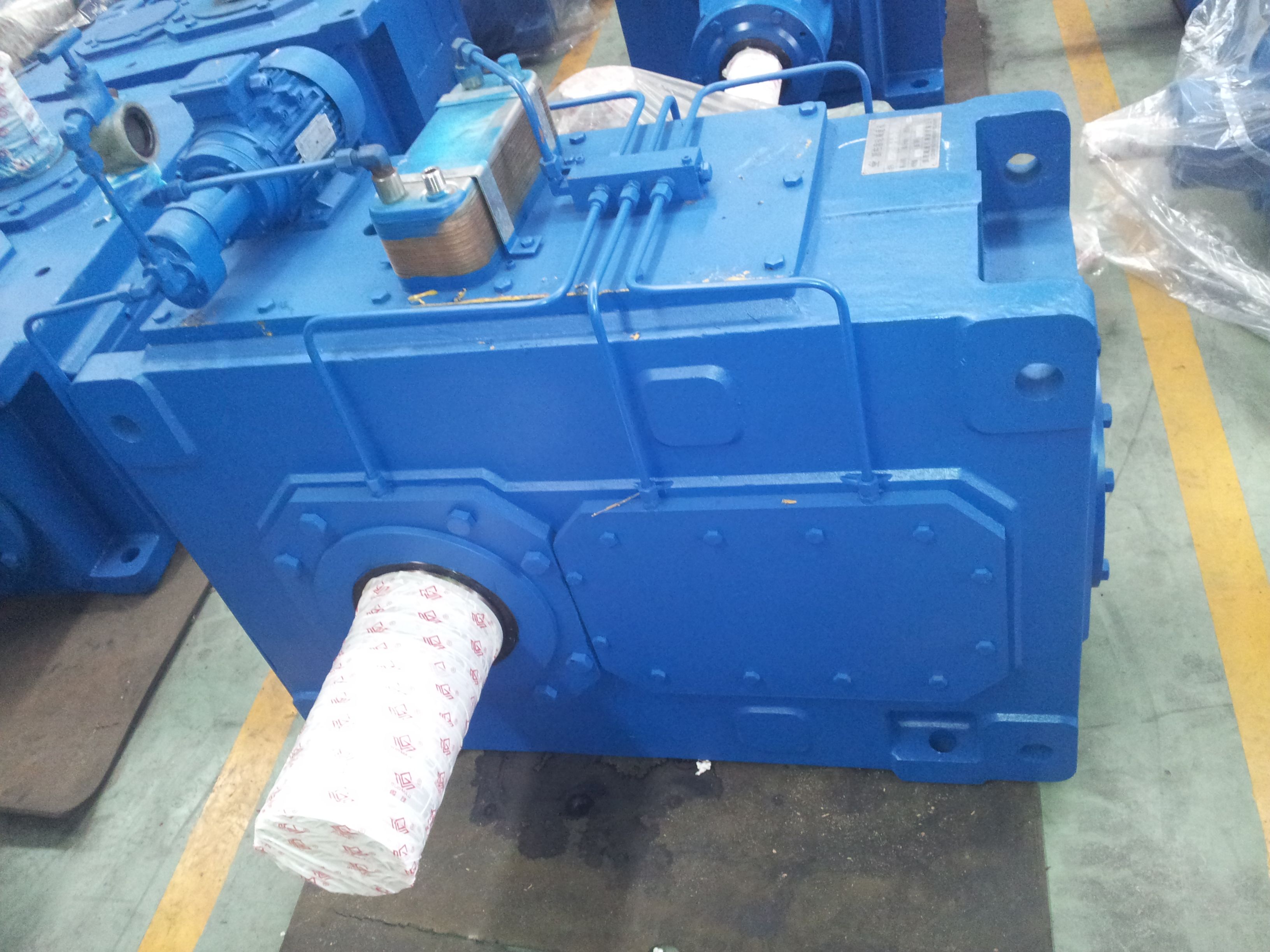
kg kg Solid shaft with parallel key HSH n B2-KV-14-D Bevel-helical gear reducer B2
In stock
SKU
B2-KV-14-D
$282,857.14
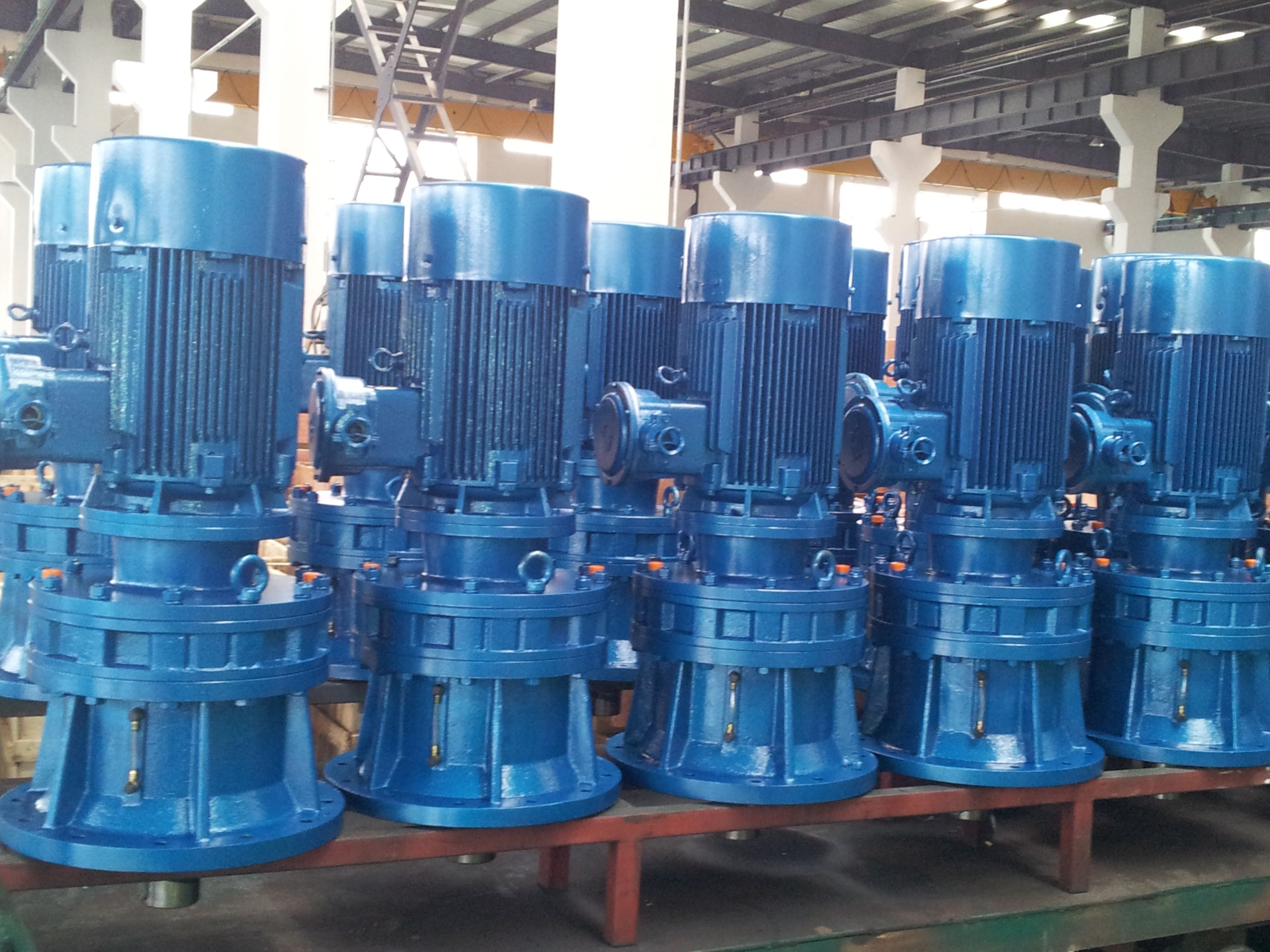
Flender/Flender Gear Units/Bevel-helical gear reducer B2
nit and its mass TN/, or ratio of gear unit speed ratio and its mass /, or more better the product of load capacity and speed ratio of gear unit devided by its mass TN / (Fig. 5, Fig. .
  Taking these parameters into the consideration, it can be concluded that the solution is more favourable from the specific loa
  capacity point of view (Fig. 5-, from the speed ratio point of view the most favoura ble solution is gear
  unit of manufacturer (Fig. 5-, and from the point of vi ew of both load capacity and speed ratio, the most favourable solution is produc ed by manufacturer (Fig. 5-. 0 1 1 0 1 2 0 4 6 8 3 $ gear units of different manufacturers (1 /, 2 max /, 3 max /) Solution is more favourable from the specific loa capacity point of view for three-stages gear units (Fig. 6-, from the speed ratio point of view the most favourable solution is gear unit of manufacturer (Fig. 6-, and from the point of view of both load capacity and speed ratio, the mos favourable solution is produced by manufacturer (Fig. 6-. Comparing these data it can be concluded that the ost favourable two- stages solution is gear unit made by manufacturer , but if only speed ratio is important, more favourable solution is made by manu facturer . The most favourable three-stages solution is gear unit also made by manufacturer , but if only load capacity is important, the better solution is , or if only speed ratio is important, TN / umax / 6.9 8.2 1.3 1.8 1 1.6 5.2 4.7 4.1 2.2 TN max / 1 6 6 7 5 ANNALS OF THE FACULTY OF ENGINEERING HUNEDOARA JO URNAL OF ENGINEERING. TOME (. Fascicole 3 2 the better solution is . Analysing all gear units, it can be concluded that manufacturer produce gear units with the most opt imal design. Also, manufacturer produce gear units with the highest values of gea ratio. 0 1 1 0 1 1 2 0 1 1 2 2 3 3 % gear unit
| Model Type | Bevel-helical gear reducer B2 |
|---|---|
| Gear Type | Bevel Helical Gear |
| Weight (kg) | 13200.000000 |
| Ratio Range | 1 : 6.3…22.4 |
| Low Speed Output | Hollow shaft with spline acc. to DIN 5480 |
| Nominal Torque | 101000 Nm |
| Mounting Arrangements | Vertical mounting position |
| Manufacturer | FLENOER-GRAFFENSTA |
| Country of Manufacture | China |
| Data Sheet & Drawings | kg kg Solid shaft with parallel key HSH n B2-KV-14-D Bevel-helical gear reducer B2 |
Related Products